Display control apparatus and method

a control apparatus and display control technology, applied in the field of display control apparatus and display control method, can solve the problems of inability to display in real time an image with plentiful motions on a display device having a low refresh rate, and the above-conventional display devi

Inactive Publication Date: 2005-11-22
CANON KK
View PDF4 Cites 21 Cited by
  • Summary
  • Abstract
  • Description
  • Claims
  • Application Information

AI Technical Summary

Benefits of technology

[0011]Under the above-described background, it is therefore an object of the present invention to provide a display control apparatus and a display control method capable of a real time display of an image with plentiful motions even on a dot matrix display device having a low refresh rate and capable of displaying even a computer signal having display modes at various resolutions or a TV signal on a dot matrix display device having a fixed resolution.

Problems solved by technology

The above-conventional display devices are, however, associated with the following problems.
In addition to this problem, another problem is that a real time display of an image with plentiful motions on a display device having a low refresh rate is impossible unless the image data has a resolution lower than the vertical resolution of the display device.

Method used


Image

  • Display control apparatus and method
  • Display control apparatus and method
  • Display control apparatus and method

Examples


first embodiment

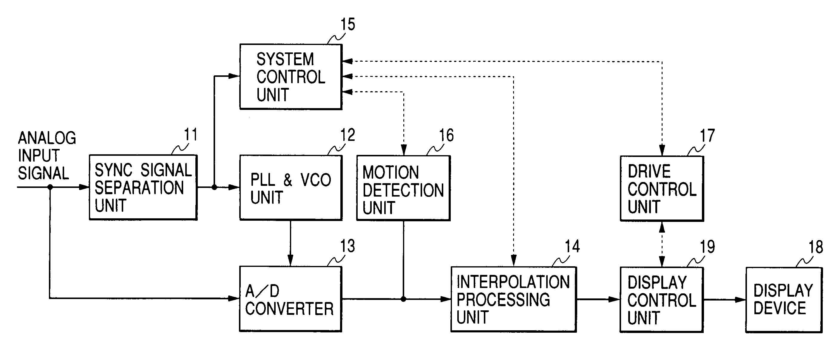
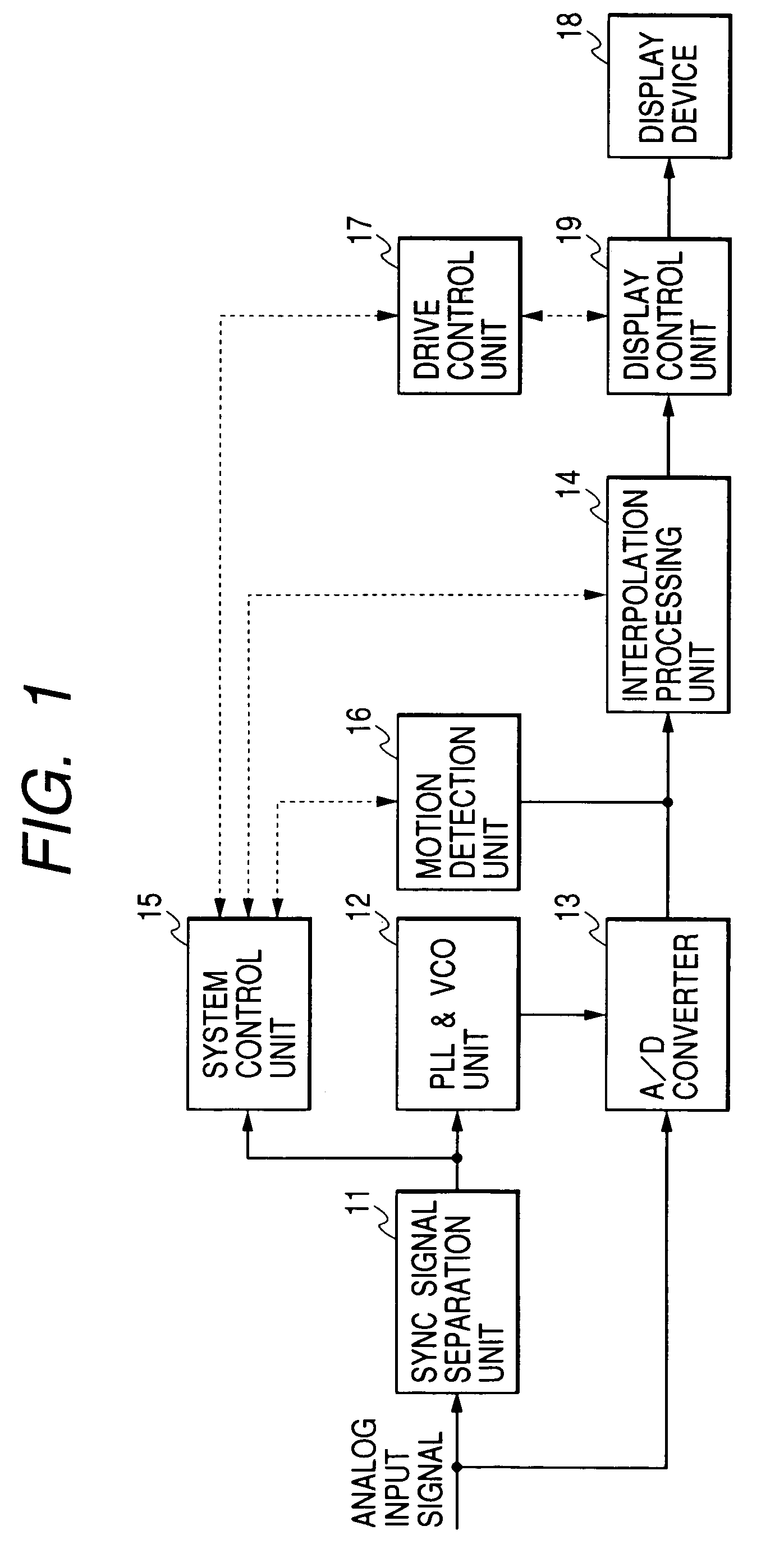
[0030]First, the structure of a display control apparatus of the first embodiment will be described with reference to FIG. 1. The display control apparatus is constituted of a sync signal separation unit 11, a PLL (phase locked loop) & VCO (voltage controlled oscillator) unit 12, an A / D (analog / digital) converter 13, an interpolation processing unit 14, a system control unit 15, a motion detection unit 16, a drive control unit 17 and a display control unit 19. The display control apparatus performs a display control of a display device 18 and is connected to a host computer (not shown) or the like.

[0031]The structure of each component of the display control apparatus will be described in detail. The sync signal separation unit 11 receives a video signal from a host computer or the like, the video signal being constituted of an RGB image signal and sync signals such as a composite sync signal, a separate sync signal and a sync-on green signal. The input video signal is separated into...

second embodiment

[0062]The structure of a display control apparatus of the second embodiment will be described with reference to FIG. 9. The display control apparatus is constituted of a sync signal separation unit 21, a PLL (phase locked loop) & VCO (voltage controlled oscillator) unit 22, an A / D (analog / digital) converter 23, an interpolation processing unit 24, a system control unit 25, an on-screen display (OSD) control unit 26, a switch 27, a key input unit 28, a drive control unit 29 and a display control unit 30. The display control apparatus performs a display control of a display device 18 and is connected to a host computer (not shown) or the like.

[0063]The structure of each component of the display control apparatus will be described in detail. The sync signal separation unit 21 receives a video signal from a host computer or the like, the video signal being constituted of an RGB image signal and sync signals such as a composite sync signal, a separate sync signal and a sync-on green sign...

third embodiment

[0074]The structure of a display control apparatus of the third embodiment will be described with reference to FIG. 11. The display control apparatus is constituted of a sync signal separation unit 71, a PLL (phase locked loop) & VCO (voltage controlled oscillator) unit 72, an A / D (analog / digital) converter 73, a switch 74, a system control unit 75, a motion detection unit 76, an interpolation processing unit 77, a key input unit 78, a drive control unit 79, a decoder unit 80, a frame conversion unit 81 and a display control unit 82. The display control apparatus performs a display control of a display device 18 and is connected to a host computer (not shown) or the like.

[0075]The structure of each component of the display control apparatus will be described in detail. The sync signal separation unit 71 receives a video signal from a host computer or the like, the video signal being constituted of an RGB image signal and sync signals such as a composite sync signal, a separate sync ...


PUM


Abstract

A display control apparatus and a display control method are provided in which a resolution of an input image signal is judged, a change in the image signal is detected, and the image signal is adaptatively interpolated in accordance with the judgement and detection results. A resolution of an input image signal is judged, either a first display mode or a second display mode is selected for the display of the image signal, and the image signal is adaptatively interpolated in accordance with the judgement and selection results. Alternatively, either a computer input signal or a television input signal is input, a resolution of the input signal is judged, and the input signal is adaptatively interpolated in accordance with the selected input and judgement results.

Description

BACKGROUND OF THE INVENTION[0001]1. Field of the Invention[0002]The present invention relates to a display control apparatus and a display control method of controlling the display of a display device such as a dot matrix display device. More particularly, the invention relates to a display control apparatus and a display control method capable of displaying an input signal on a display device even if the input signal has a different resolution from that of the display device.[0003]2. Related Background Art[0004]Raster scan type CRT display devices are widely used with host computers such as personal computers and work stations. Flat panel display devices such as liquid crystal panel display devices and plasma display devices have recently drawn much attention from the viewpoint of space reduction, energy savings and ergonomics (methodology of configuring a system to suit human characteristics by studying optimum working environments).[0005]Between a host computer and a CRT display ...

Claims


Application Information

Patent Timeline
Patent Type & Authority Patents(United States)
IPC IPC(8): G06F3/14G06T17/10G09G5/00G09G5/36G09G3/20G09G3/36H04N7/01H04N11/06H04N5/08H04N5/66H04N11/20
CPCG09G5/006H04N7/0135G09G5/008G09G2320/103G09G2340/0414G09G2340/0421
Inventor SUGA, KAZUMI
Owner CANON KK
Why Eureka
Try Eureka