Hybrid optical transceivers for free space optical communication

a technology of optical communication and optical transceivers, applied in the direction of line-of-sight transmission, instruments, optical elements, etc., can solve the problems of inability to economically configure to reach, disruptive and laborious installation of such systems in existing buildings, and several practical limitations, etc., to achieve the effect of being ready to adap

Inactive Publication Date: 2005-11-22
OL SECURITY LIABILITY CO
View PDF21 Cites 16 Cited by
  • Summary
  • Abstract
  • Description
  • Claims
  • Application Information

AI Technical Summary

Benefits of technology

[0003]Free space optical communication systems do not exhibit the limitations associated with the installation and maintenance of guided wave optical communication systems. Such systems include optical transmitters and receivers that are configured to de...

Problems solved by technology

While guided wave optical systems have become commonplace in telecommunications, such systems exhibit several practical limitations.
Installation of such systems in existing buildings can be disruptive and labor intensive, and in some cases cannot be economically configured to reach all building areas for which optical communication services are desired.
Installation in either of these manners can be slow and expensive.
In addition, reconfiguration of a guided wave communication system can be difficult as additional optical fiber or other waveguide must be installed to reach any newly selected locations.
As a result, an installed communication system can require expensive upgrades.
While fre...

Method used


Image

  • Hybrid optical transceivers for free space optical communication
  • Hybrid optical transceivers for free space optical communication
  • Hybrid optical transceivers for free space optical communication

Examples


Embodiment Construction

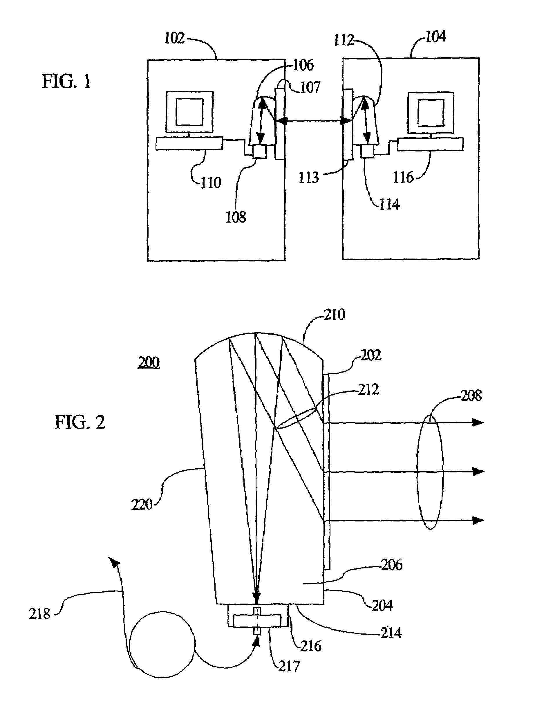
[0030]With reference to FIG. 1, a communication system is configured to transmit data, voice, or other information between buildings 102, 104. An optical transceiver 106 is situated at or near a window 107 and is configured to transmit optical signals produced by an optical transmitter / receiver module 108 to the building 104. The optical transceiver 106 is also configured to receive optical signals from the building 104 and direct the received optical signals to the optical transmitter / receiver module 108. The received optical signals are converted to electrical signals at the transmitter / receiver module 108 or can be deliver by an optical fiber or other optical apparatus to a server 110 that includes electrical-to-optical and / or optical-to-electrical conversion circuitry. The associated electrical signal is then processed by the server 110 or other computer or network element.

[0031]An optical transceiver 112 is similarly configured at the building 104 for communication with...


PUM


Abstract

Optical transceivers include a diffractive optical element (DOE) attached to a surface of a prism or other optical support. The DOE is configured to direct an input optical signal to a curved reflective surface or receive an output optical signal from the curved reflective surface at angles greater than a critical angle. In some examples, the optical support includes one or more curved reflective surfaces and the DOE is a hologram. Such optical transceivers can be provided with optical mounts configured for attachment to a building window.

Description

TECHNICAL FIELD[0001]The invention pertains to methods and apparatus for free space optical communication.BACKGROUND AND SUMMARY[0002]While guided wave optical systems have become commonplace in telecommunications, such systems exhibit several practical limitations. Installation of such systems in existing buildings can be disruptive and labor intensive, and in some cases cannot be economically configured to reach all building areas for which optical communication services are desired. Communication applications between two or more buildings or other locations typically require underground installation of optical cables in existing utility tunnels or burial in newly dug trenches. Installation in either of these manners can be slow and expensive. In addition, reconfiguration of a guided wave communication system can be difficult as additional optical fiber or other waveguide must be installed to reach any newly selected locations. As a result, an installed communication system can re...

Claims


Application Information

Patent Timeline
IPC IPC(8): G02B6/42H04B10/24H04B10/10H04B10/112H04B10/40
CPCG02B6/4206H04B10/1125H04B10/40
Inventor BRATT, NICHOLAS E.FADLOVICH, CHACE H.PIERCE, ROBERT M
Owner OL SECURITY LIABILITY CO
Why Eureka
Try Eureka