Optical arrangement and scan microscope

a scanning microscope and optical arrangement technology, applied in the field of optical arrangement and scanning microscope, can solve the problems of high high cost of arrangement that requires three additional optical components for compensation, and detrimental splitting of detection light beam, so as to simplify the adjustment of optical arrangement or scanning microscope, avoid loss of detection light output, and easy replacement

Inactive Publication Date: 2005-11-22
LEICA MICROSYSTEMS CMS GMBH
View PDF12 Cites 10 Cited by
  • Summary
  • Abstract
  • Description
  • Claims
  • Application Information

AI Technical Summary

Benefits of technology

[0021]In a preferred embodiment, a device to effectuate a displacement of the beam is arranged downstream from the acousto-optical component and from the compensation element. As a result, the axis of the detection light beam entering the optical arrangement is coaxial or at least parallel to the axis of the detection light beam leaving the optical arrangement. This simplifies the adjustability of the optical arrangement or of the scanning microscope; furthermore, the arrangement in a scanning microscope can be more easily replaced by a conventional beam splitter in this configuration.
[0022]In a preferred embodiment, the acousto-optical component is cemented to the compensation element. In another embodiment, an intermediate element is provided that is cemented to the acousto-optical component and to the compensation element. The cemented embodiments entail the advantage that it is possible to largely avoid losses of detection light output caused by reflections on the boundary surfaces of the acousto-optical component and of the compensation element that face each other. Preferably, there is an entrance window for an illumination light beam on the intermediate element.

Problems solved by technology

A drawback of optical arrangements having an acousto-optical component for separating the illuminating light and the detection light as well as of scanning microscopes having an acousto-optical component for separating the illuminating light and the detection light lies in the fact that the acousto-optical component is birefringent, which leads to a detrimental splitting of the detection light beam.
The known arrangements do not compensate for this effect adequately and they entail high losses of detection light output.
Especially arrangements that call for three additional optical components for the compensation are expensive and their adjustment is complex.

Method used


Image

  • Optical arrangement and scan microscope
  • Optical arrangement and scan microscope
  • Optical arrangement and scan microscope

Examples


Embodiment Construction

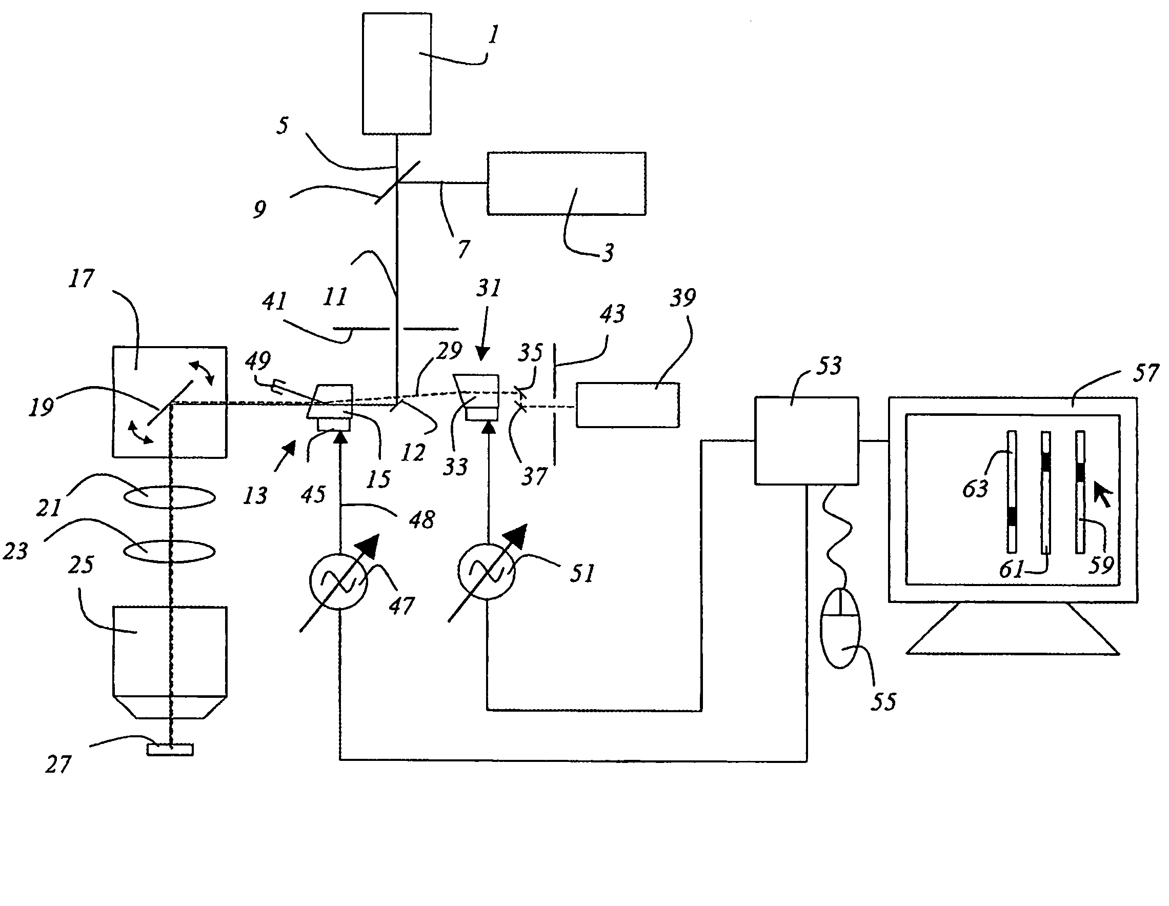
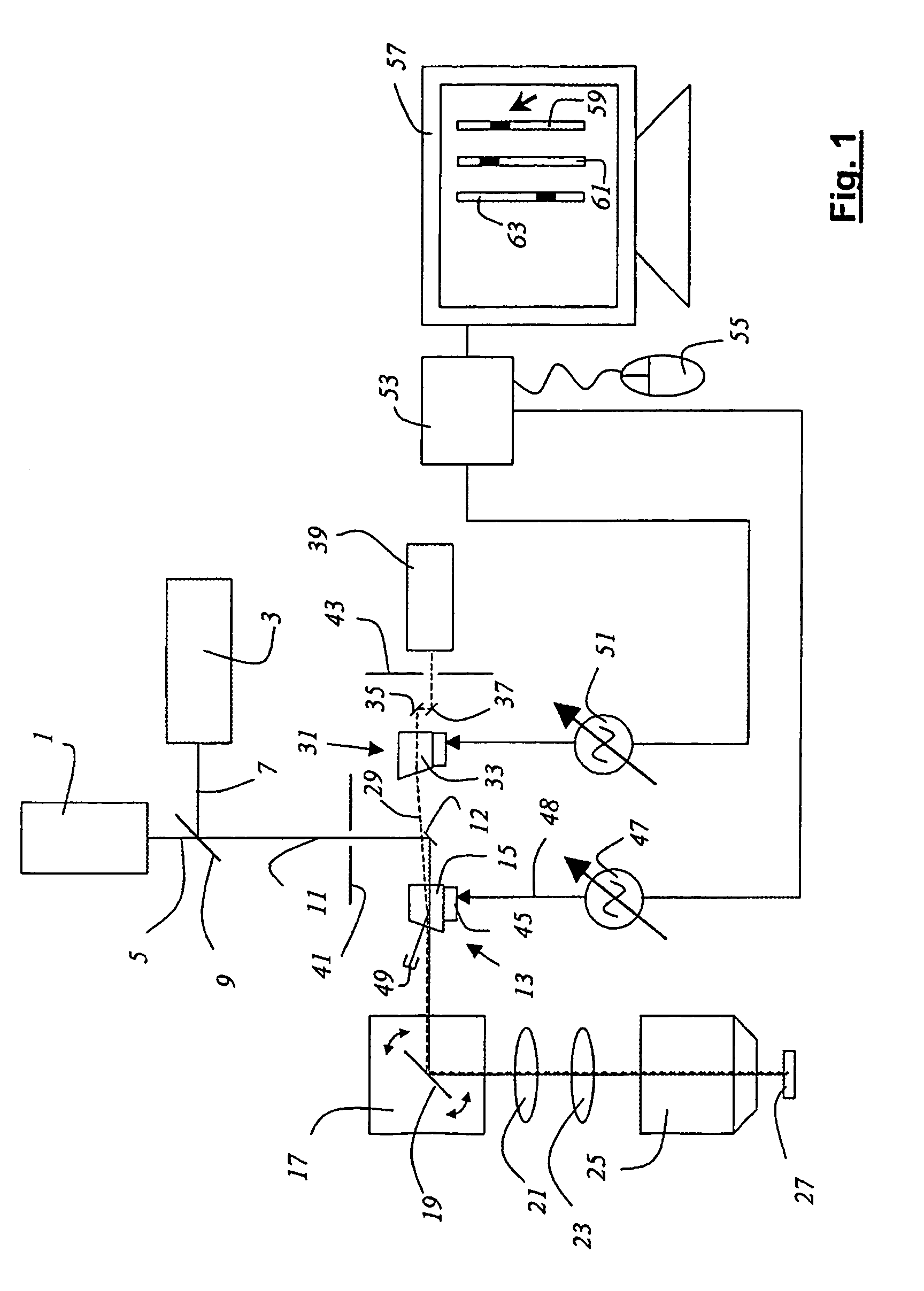
[0029]FIG. 1 shows a scanning microscope according to the invention, which is configured as a confocal microscope, having two lasers 1, 3 whose emission light beams 5, 7, which have different wavelengths, are combined with the dichroitic beam recombiner 9 so as to form one illumination light beam 11. The scanning microscope has an acousto-optical component 13 that is configured as an AOTF 15. The illumination light beam 11 is reflected by a reflecting mirror 12 towards the acousto-optical component 13. From the acousto-optical component 13, the illumination light beam 11 reaches a beam deflection means 17 that contains a gimbal-mounted scanning mirror 19 and guides the illumination light beam 11 through the scanning lens system 21, through the tubular lens system 23 and through the objective lens 25 over or through the specimen 27. The detection light beam 29 coming from the specimen passes in the reverse direction through the scanning lens system 21, through the tubular lens system...


PUM

PropertyMeasurementUnit
birefringenceaaaaaaaaaa
optical arrangementaaaaaaaaaa
dispersionaaaaaaaaaa

Abstract

An optical arrangement for spatially separating an illumination light beam and a detection light beam includes an acousto-optical component that splits the detection light beam by birefringence. A compensation element is provided that compensates, in a single passage of the detection light beam, for the splitting of the detection light beam.

Description

[0001]The invention relates to an optical arrangement for spatially separating an illumination light beam and a detection light beam, with an acousto-optical component.[0002]Furthermore, the invention relates to a scanning microscope having a light source that generates an illumination light beam and having a detector that picks up a detection light beam coming from a specimen, and also having an acousto-optical component for spatially separating the illumination light beam and the detection light beam.BACKGROUND[0003]In scanning microscopy, a specimen is illuminated with a light beam in order to observe the detection light emitted by the specimen as reflection or fluorescent light. The focus of an illumination light beam is moved in a specimen plane by means of a controllable beam deflector, normally by tilting two mirrors, whereby the deflection axes are usually at right angles with respect to each other so that one mirror deflects in the x direction while the other deflects in th...

Claims


Application Information

Patent Timeline
Patent Type & Authority Patents(United States)
IPC IPC(8): G02B21/00G02F1/11
CPCG02B21/0024G02B21/0032G02B21/008
Inventor BIRK, HOLGER
Owner LEICA MICROSYSTEMS CMS GMBH
Why Eureka
Try Eureka