
Method for inserting cochlear electrode and insertion tool for use therewith

a cochlea electrode and electrode technology, applied in the field of electrode arrays, can solve the problems of conductive hearing loss, impede the normal mechanical pathway for sound to reach the hair cells in the cochlea, and deafness sensorineural hearing loss, and achieve the effect of facilitating the space-filling electrode system, minimal effort, and no serious risk of injury or trauma to the cochlea or

Inactive Publication Date: 2005-11-22
BOSTON SCI NEUROMODULATION CORP
View PDF21 Cites 114 Cited by
  • Summary
  • Abstract
  • Description
  • Claims
  • Application Information

AI Technical Summary

Benefits of technology

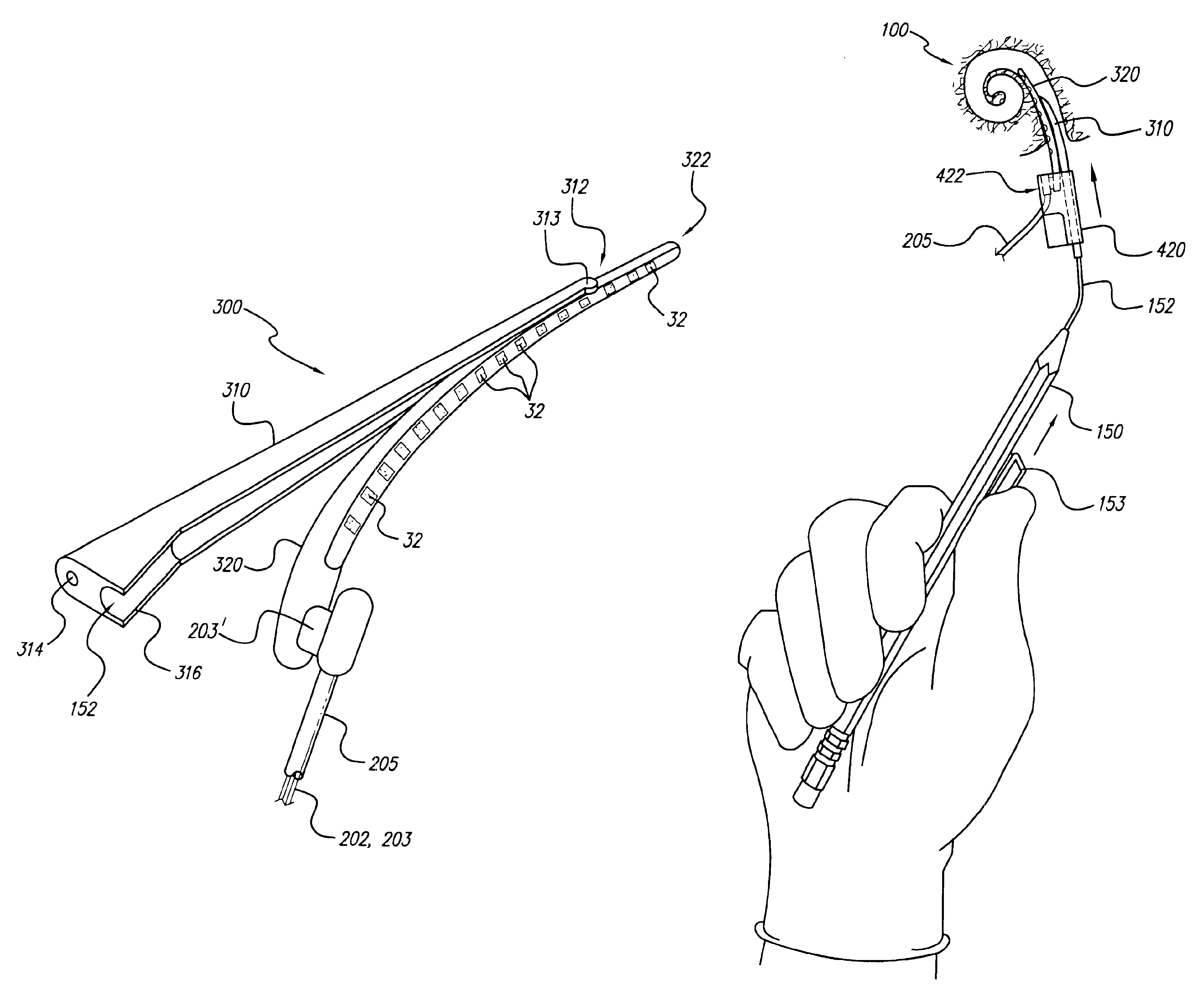
[0016]The present invention addresses the above and other needs by providing a universal electrode array system, adapted for insertion into either a left or right cochlea, which provides improved stability of electrode contact direction. Such universal electrode array system includes a cochlear electrode array, e.g., of the type disclosed in Applicant's U.S. Pat. No. 6,129,753, incorporated herein by reference, combined with an electrode positioner, e.g., a straightened version of the type disclosed in Applicant's U.S. Pat. No. 6,078,841, also incorporated herein by reference. Advantageously, in accordance with the present invention, such electrode array and positioner are combined as a single system, with a distal tip of the positioner being joined to the electrode array near the distal tip of the electrode array. Thus, as one of the elements is inserted into the scala tympani duct of the cochlea, the other element is carried with it, allowing both elements of the system to be jointly inserted into the cochlea during a single implant operation. Such insertion is facilitated using an easy-to-use insertion tool, which insertion tool also comprises part of the present invention.
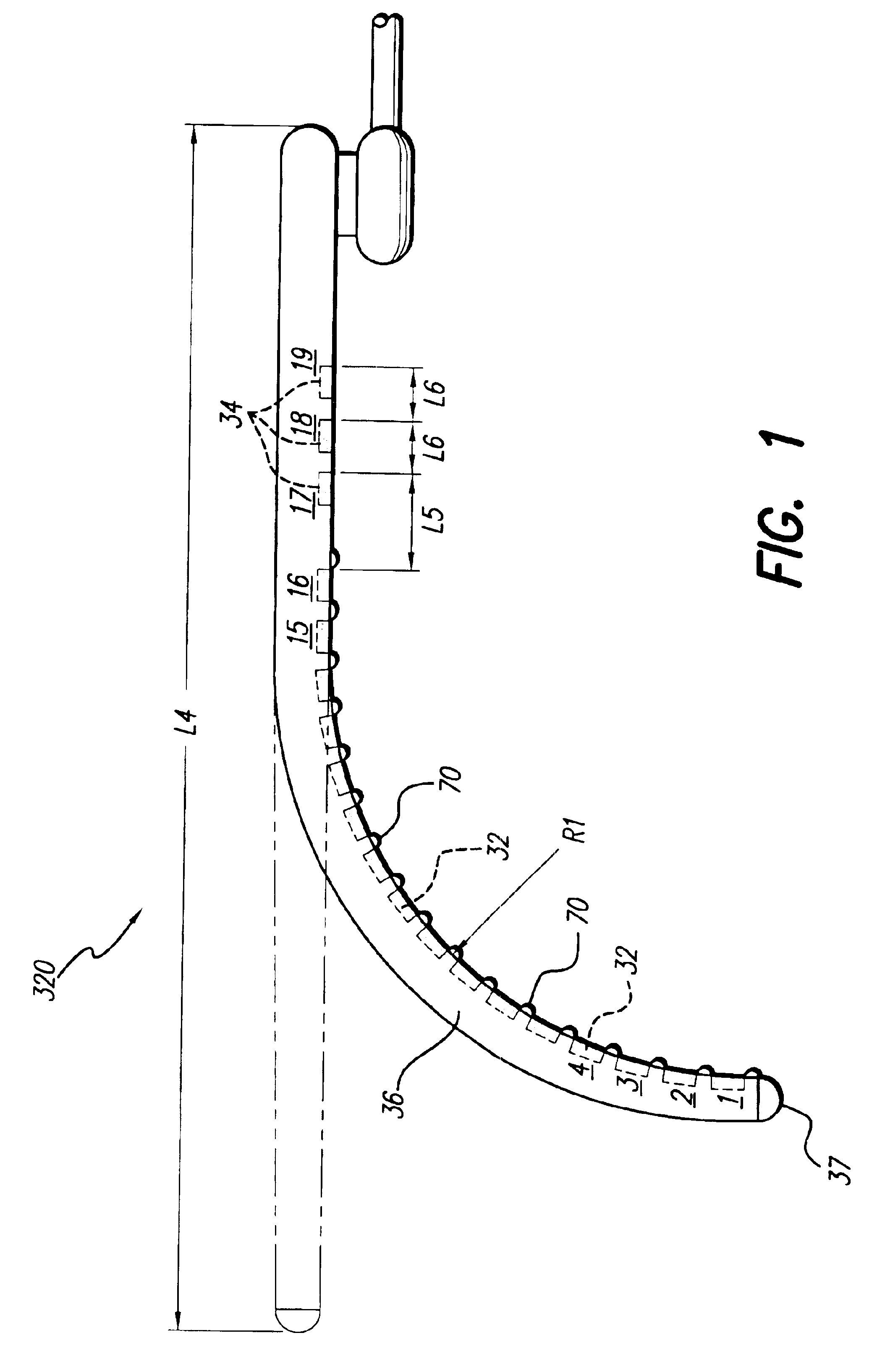
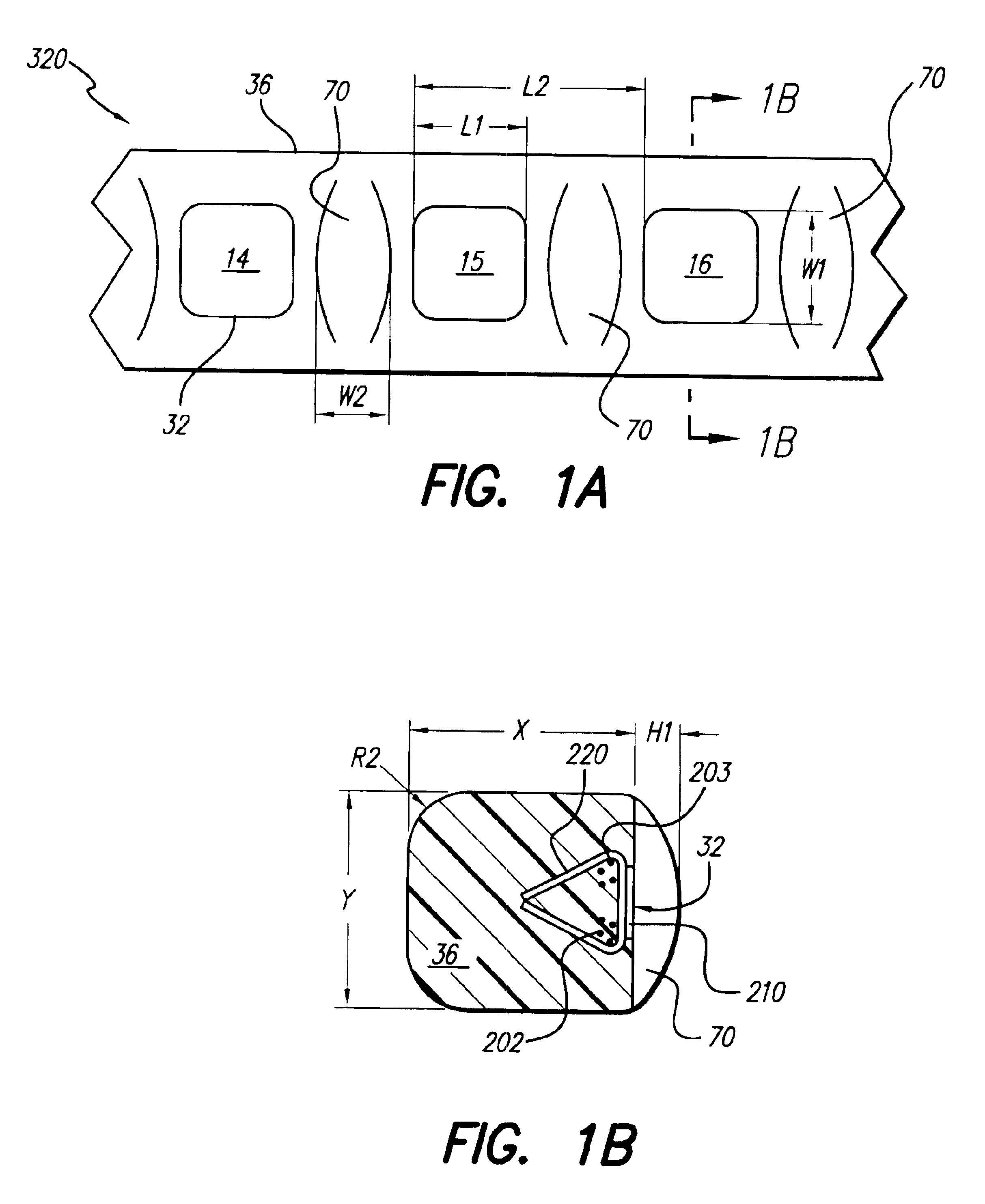
[0017]In accordance with one aspect of the present invention, the electrode array component of the electrode system preferably has all of the electrode contacts spaced apart along one edge or side of the array, termed the “medial side”. In a preferred embodiment, the structure of the electrode array facilitates bending of the array with the electrode contacts on the inside of the bend, yet deters flexing or twisting of the array that would tend to position or point the electrode contacts away from the inside of the bend. Hence, when inserted into the scala tympani duct of a cochlea, all of the electrode contacts on the medial side of the array generally face the modiolus wall of the cochlea.
[0020]In accordance with a still further aspect of the invention, a preferred insertion tool uses a stylet wire that is threaded into a lumen or channel that passes longitudinally through the positioner. A specially configured guiding tube holds and maintains the positioner in its desired location along a back side of the electrode array (opposite the medial side) during the insertion procedure. The stylet wire, with the positioner component of the system threaded thereon, is gently guided and pushed, as required, in order to steer and slide the positioner, and the electrode array which is connected to it, into the scala tympani (or other duct) of the cochlea to the desired depth. Advantageously, the guiding tube holds the electrode array in a parallel position to the positioner during the initial placement of the electrode system within the cochlea, and in particular during the first 3-4 mm of advancement of the electrode system past the first turn of the scala tympani. Because the distal tip of the electrode array protrudes distally a short distance beyond the point where the distal tip of the positioner joins the electrode array, the protruding distal tip of the electrode array may function as a soft bumper as the electrode assembly is slid into and through the bends of the spiraling cochlea, thereby minimizing the risk of any serious damage or trauma to the cochlea or the patient as the implant operation is carried out.
[0021]In accordance with still a further aspect of the invention, both components of the electrode system of the present invention—the universal electrode array and the positioner—are manufactured using easy, low cost technology; and once made can be easily inserted, removed and reinserted, if required, into the cochlea or other curved body cavity.
[0022]Advantageously, the cochlear electrode system of the present invention achieves the following goals: (1) it assures that the electrode contacts of the electrode array are optimally positioned facing the medial direction, e.g., facing the modiolar wall in a cochlea of any size or any side (left or right) of the body; (2) it assures the electrode contacts, or alternatively the non-conductive humps or bumps (if used) between the electrode contacts, are positioned against the modiolar wall; (3) it may be manufactured using easy, low cost technology; (4) it may be easily inserted into the cochlea, and removed and reinserted, if required; and (5) it allows both the electrode array and positioner to be simultaneously inserted into the cochlea using a convenient simple-to-use insertion tool.
[0024]It is a further feature of the invention to provide an easy-to-use insertion tool that may be used to facilitate insertion of the space-filling electrode system into the cochlea with minimal effort and without serious risk of injury or trauma to the cochlea or the patient.

Problems solved by technology

Of these, conductive hearing loss occurs where the normal mechanical pathways for sound to reach the hair cells in the cochlea are impeded, for example, by damage to the ossicles.
In many people who are profoundly deaf, however, the reason for their deafness is sensorineural hearing loss.
These people are unable to derive any benefit from conventional hearing aid systems, no matter how loud the acoustic stimulus is made, because their mechanisms for transducing sound energy into auditory nerve impulses have been damaged.
Thus, in the absence of properly functioning hair cells, there is no way auditory nerve impulses can be generated directly from sounds.
In practice, this goal tends to be difficult to realize because of the anatomy of the cochlea.
Unfortunately, while the electrode array with spiral-shaped carrier shown in the '647 patent represents a significant advance in the art, there exists lack of sufficient shape memory associated with the carrier to allow it to return to its original curvature (once having been straightened for initial insertion) with sufficient hugging force to allow it to wrap snugly against the modiolus of the cochlea.
While the electrode array taught In the above-referenced '219 and '585 patents has the right idea, i.e., to force the electrode carrier into a close hugging engagement with the modiolus, it does so only by use of a system that makes manufacture of the lead more difficult and expensive, and only through application of an additional pushing force which is applied to an electrode structure after it is already fully inserted into the cochlea.
Such additional pushing force may easily cause damage to the delicate scala tympani.
Moreover, the entire electrode array may twist during the insertion process, or when the additional pushing force is applied, thereby causing the electrode contacts to twist and / or be forced away from the modiolus, rather than in a hugging relationship therewith.
Thus, it is seen that while it is known that enhanced performance of a cochlear implant may be achieved by proper placement of the electrode contacts close to the modiolar wall of the cochlea, two main problems have faced designers in attempting to achieve this goal.
First, it is extremely difficult to assemble electrode contacts on the medial side of the an electrode array, facing the modiolus of the cochlea.
Second, heretofore there has either been the need for application of an external (and perhaps unsafe) force, or a lack of sufficient shape memory, to allow the electrode (after initial straightening to facilitate insertion) to assume or return to the desired curvature needed to place the electrodes against the modiolar wall so that the curvature wraps snugly around the modiolus of the cochlea.
As a result, the electrode contacts of the prior art electrodes generally remain positioned too far way from the modiolar wall.

Method used


Image

  • Method for inserting cochlear electrode and insertion tool for use therewith
  • Method for inserting cochlear electrode and insertion tool for use therewith
  • Method for inserting cochlear electrode and insertion tool for use therewith

Examples


Embodiment Construction

[0050]The following description is of the best mode presently contemplated for carrying out the invention. This description is not to be taken in a limiting sense, but is made merely for the purpose of describing the general principles of the invention. The scope of the invention should be determined with reference to the claims.

[0051]The invention described herein teaches a particular type of implantable electrode array system intended for use with a cochlear stimulation system. The electrode system of the present invention is designed to be inserted deep into the cochlea of the user of the cochlear stimulation system.

[0052]The electrode system of the present invention is made from two main components: (1) an electrode array having electrode contacts, and (2) a positioner joined at its distal tip to the electrode array near its distal tip. Because each of the components of the electrode system described herein may be made separately, and joined together later, and each component af...


PUM


Abstract

An implantable electrode system, adapted for insertion into a cochlea, includes an elongate electrode array stored within a sheath. The electrode array has a multiplicity of electrode contacts carried on a flexible elongate carrier, which carrier is adapted for insertion into one of the spiraling ducts, e.g., the scala tympani, of the cochlea, and further has longitudinal channel or lumen that passes therethrough. 3-6 mm from the distal end of the electrode array. To insert the electrode system into the cochlea, a stylet wire is inserted into the channel or lumen of the electrode array while the electrode array is held within the sheath. The sheath is then removed, and the electrode array is then gently guided and pushed through a cochleostomy into the cochlea by extending the stylet wire to a desired depth. As the electrode array is thus inserted into the cochlea, the stylet wire is retracted and the electrode array remains implanted within the cochlea.

Description

[0001]The present application is a Continuation of U.S. application Ser. No. 09 / 706,233, filed Nov. 3, 2000 now abandoned, which application is a continuation-in-part (CIP) of U.S. application Ser. No. 09 / 559,606, filed Apr. 27, 2000 now abandoned; which is a CIP of application Ser. No. 09 / 298,410, filed Apr. 23, 1999, U.S. Pat. No. 6,195,586; which is a CIP of application Ser. No. 09 / 140,034, filed Aug. 26, 1998, U.S. Pat. No. 6,038,484; which patents and applications are incorporated herein by reference.[0002]The subject matter of this application is closely related to the subject matter of U.S. application Ser. No. 09 / 443,628, filed Nov. 19, 1999, U.S. Pat. No. 6,321,125, which patent is also incorporated herein by reference.BACKGROUND OF THE INVENTION[0003]The present invention relates to implantable stimulation devices, e.g., cochlear prosthesis used to electrically stimulate the auditory nerve, and more particularly to an electrode array for use with a cochlear stimulator that...

Claims


Application Information

Patent Timeline
IPC IPC(8): A61N1/05
CPCA61N1/0541A61B17/3468A61B2017/00787
Inventor KUZMA, JANUSZ A.
Owner BOSTON SCI NEUROMODULATION CORP
Learn More