Sector staging combustor

a combustor and stage technology, applied in the direction of engine starters, ignition of turbine/propulsion engines, lighting and heating apparatus, etc., can solve the problems of increasing the complexity of the pressure injector, and increasing the difficulty of starting

Inactive Publication Date: 2005-11-29
GENERAL ELECTRIC CO
View PDF31 Cites 51 Cited by
  • Summary
  • Abstract
  • Description
  • Claims
  • Application Information

AI Technical Summary

Benefits of technology

[0012]Accordingly, it is desired to provide an improved combustor for a

Problems solved by technology

Although the gas turbine engines used in these various applications are fundamentally similar in configuration, they nevertheless must be specifically tailored for those different applications and the different problems associated therewith.
Starting is particularly difficult because battery powered, low energy starters must be used to save vehicle weight, and starting requires acceleration of the turbine and compressor rotor to a major percentage of maximum rotor speed representing steady state idle.
This problem is further in

Method used


Image

  • Sector staging combustor
  • Sector staging combustor
  • Sector staging combustor

Examples


Embodiment Construction

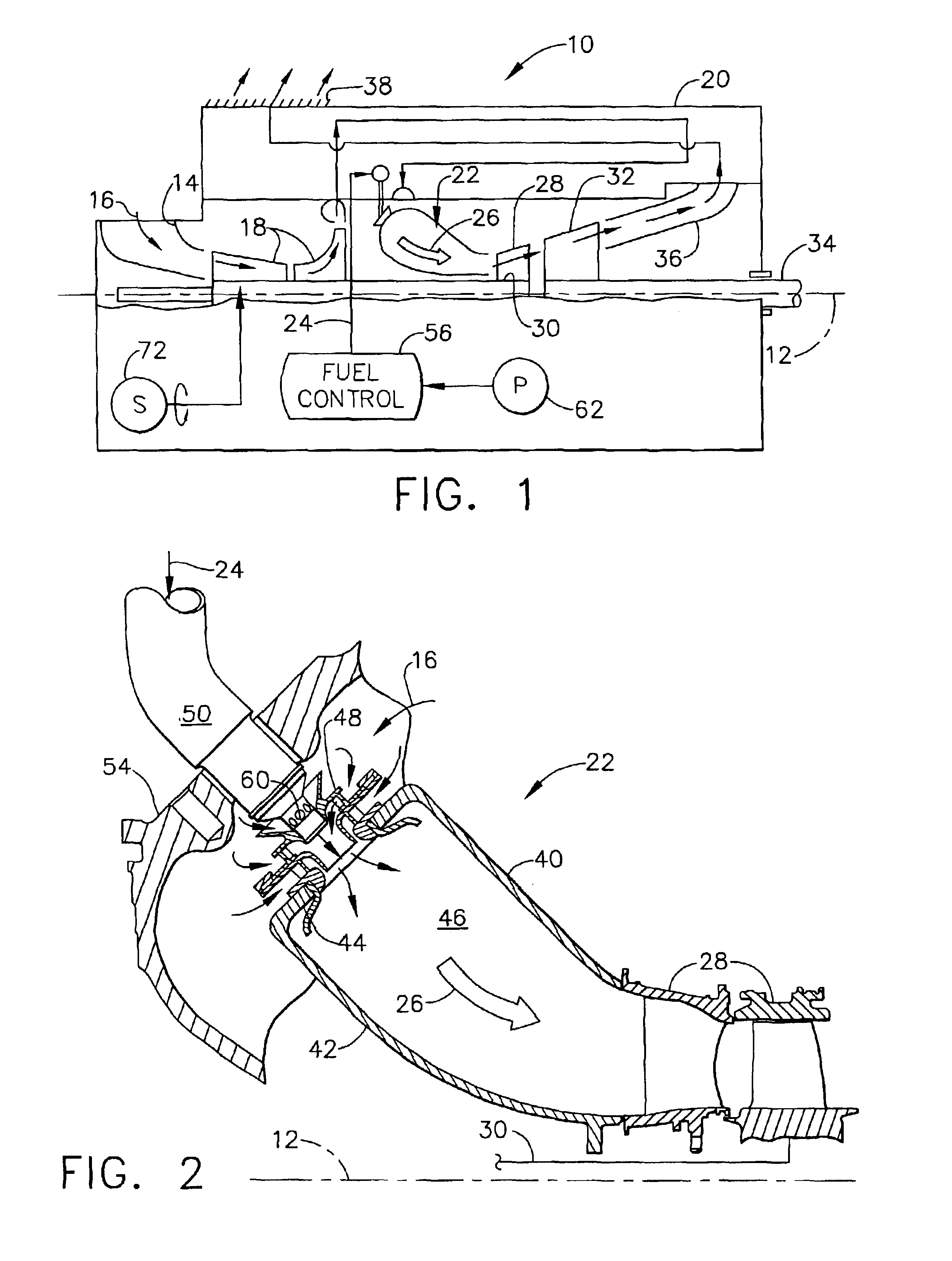
[0020]Illustrated schematically in FIG. 1 is a gas turbine engine 10 specifically configured for use in a land-based vehicle (not shown) for providing propulsion power therefor. The engine is axisymmetrical about a longitudinal or axial centerline axis 12 and includes at an upstream end an inlet 14 for receiving ambient air 16.

[0021]Following the inlet is a multistage, axi-centrifugal compressor 18 that pressurizes the air 16 which is then discharged therefrom into a surrounding recuperator or heat exchanger 20. The compressor discharge air is heated in the recuperator, as further described hereinbelow, and suitably returned to the upstream end of an annular combustor 22.

[0022]Fuel 24 is mixed with the pressurized air 16 and ignited in the combustor for generating hot combustion gases 26 therein which are discharged from the downstream, outlet end thereof to a single stage high pressure turbine (HPT) 28. The rotor disk of the HPT 28 is suitably joined to a first rotor or shaft 30 wh...


PUM


Abstract

A combustor includes outer and inner liners joined together by a dome to define a combustion chamber. A row of air swirlers is mounted in the dome and includes corresponding main fuel injectors for producing corresponding fuel and air mixtures. Pilot fuel injectors fewer in number than the main injectors are mounted in the dome between corresponding ones of the swirlers. Staged fuel injection from the pilot and main injectors is used for starting the combustor during operation.

Description

[0001]The U.S. Government may have certain rights in this invention in accordance with Contract No. DAAE07-00-C-N086 awarded by the Department of the Army.BACKGROUND OF THE INVENTION[0002]The present invention relates generally to gas turbine engines, and, more specifically, to land vehicle turbine engines.[0003]In a gas turbine engine, air is pressurized in a compressor and mixed with fuel in a combustor for generating hot combustion gases from which energy is extracted by downstream turbine stages. A high pressure turbine (HPT) immediately follows the combustor and is joined by a first rotor or shaft to the upstream compressor which typically includes multiple stages. A low pressure turbine (LPT) is disposed downstream of the HPT and produces output power for a second rotor or driveshaft.[0004]In a typical turbofan engine, the LPT is joined to a large fan in front of the compressor for producing propulsion thrust for powering an aircraft in flight. In a land or marine-based engine...

Claims


Application Information

Patent Timeline
IPC IPC(8): F23R3/34
CPCF23R3/343F23D2900/00014
Inventor HOWELL, STEPHEN JOHNJACOBSON, JOHN CARLMCCAFFREY, TIMOTHY PATRICKBARNES, BARRY FRANCIS
Owner GENERAL ELECTRIC CO
Why Eureka
Try Eureka