Axial piston machines

a technology of axial pistons and machines, which is applied in the direction of reciprocating piston engines, positive displacement engines, gas turbine engines, etc., can solve the problems of no prior effort in the marketplace, and the implementation of axial piston engines is in the provided means, so as to reduce friction losses in internal combustion engines

Inactive Publication Date: 2005-11-29
INNOVATION ENG
View PDF144 Cites 26 Cited by
  • Summary
  • Abstract
  • Description
  • Claims
  • Application Information

AI Technical Summary

Benefits of technology

[0007]It is an object of the invention to reduce friction losses in internal combustion engines and the like.
[0009]A further object of the invention is to provide a piston motion that is harmonic in nature and can be readily balanced and thereby reduce vibration.
[0010]It is an additional object of the invention to provide an improved means for preventing the rotation of the motion converter in an axial piston machine.
[0011]Another object of the invention is to provide a means for preventing the rotation of the connecting rods in an axial piston machine.

Problems solved by technology

The theoretical advantages of the axial piston arrangement have been well understood for many years, but no prior effort has succeeded in the marketplace.
The primary difficulty in implementing an axial piston engine is in the means provided for preventing rotation of the motion converter, or as commonly referred to, the “wobble plate.”

Method used


Image

  • Axial piston machines
  • Axial piston machines
  • Axial piston machines

Examples


Embodiment Construction

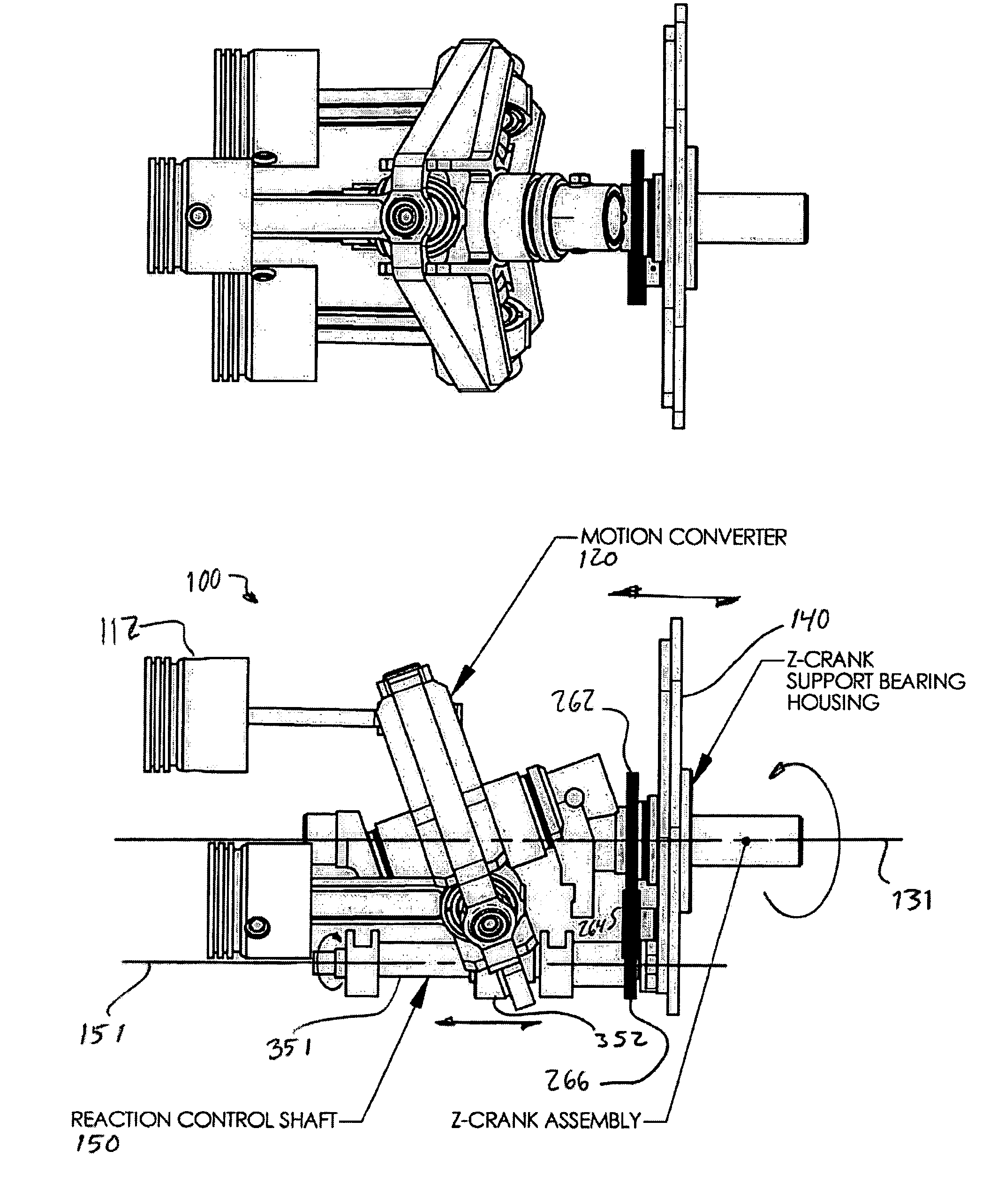
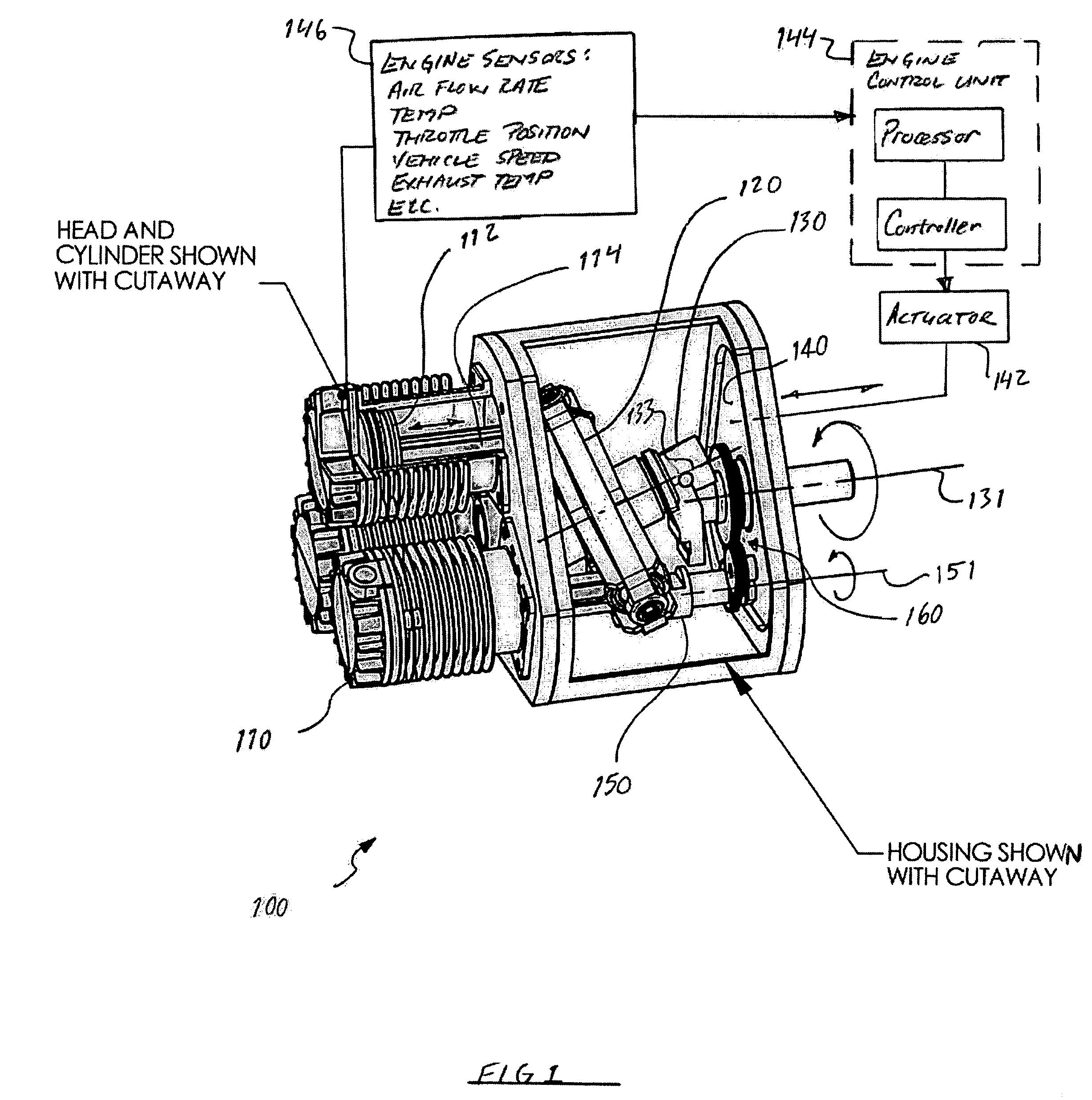
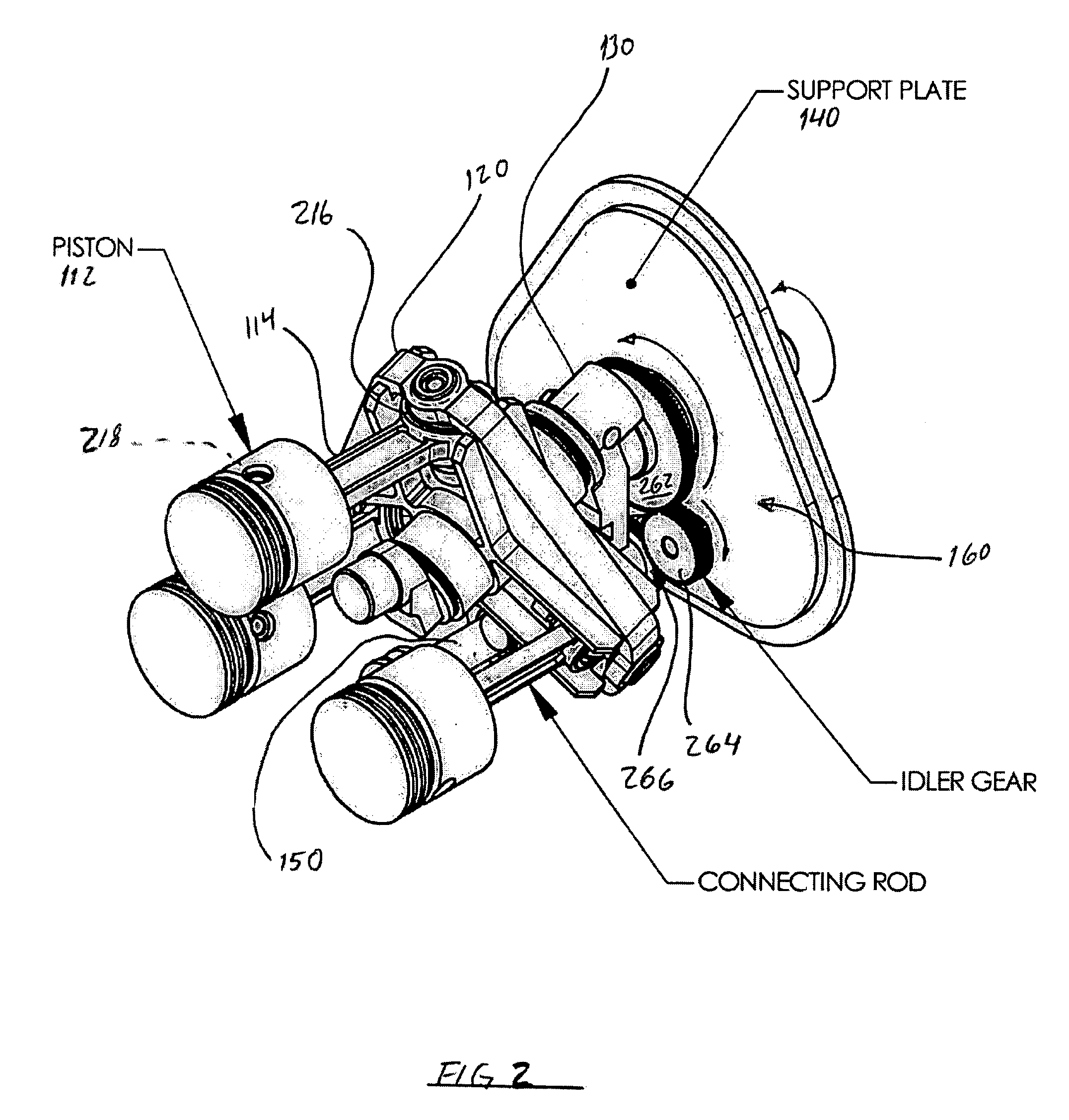
[0031]The following disclosure is directed to apparatuses and methods for converting reciprocal linear motion of one or more pistons into rotary motion of an output power shaft whose rotational axis is parallel to ther motions of the pistons or, conversely, for converting rotary motion of a similarly configured input shaft into reciprocal linear motion of one or more pistons. Various embodiments of the invention can be applied to internal combustion engines, external combustion engines, air compressors, air motors, liquid fluid pumps, and the like where movement of a working fluid within a volume-changing cylinder results from / in rotary motion of an input / output shaft. In contrast to conventional engines, compressors, and pumps where the crankshaft's rotational axis is perpendicular to the motions of the pistons, an axial piston apparatus configured in accordance with embodiments of the present invention can have one or more cylinders aligned in parallel with the rotational axis of ...


PUM


Abstract

This invention relates to internal combustion engines with cylinders arranged parallel to the main shaft and where reciprocating movements of the pistons are converted to rotation by means of a Z-crank mechanism and motion converter, or conversely to systems such as pumps and compressors wherein rotation of the Z-crank and motion converter produces reciprocating motions of the pistons. The motion converter is prevented from rotation by a reaction control shaft or by a gear train. Connecting rods are prevented from rotating about their long axes. Double-ended configurations can be either opposed cylinder or opposed piston, and may include multiple pairs of pistons with each pair in a common cylinder. The Z-crank may be moved axially for the purpose of varying the compression ratio. Variation of the compression ratio is controlled by an engine control unit and is adjusted to optimize engine performance under varying loads and other conditions.

Description

CROSS REFERENCE TO RELATED APPLICATIONS[0001]NOT APPLICABLESTATEMENT REGARDING FEDERALLY SPONSORED RESEARCH OR DEVELOPMENT[0002]NOT APPLICABLEREFERENCE TO SEQUENCE LISTING, A TABLE, OR A COMPUTER PROGRAM LISTING COMPACT DISK APPENDIX[0003]NOT APPLICABLEBACKGROUND OF THE INVENTION[0004]The following disclosure relates generally to machines and apparatuses having axial piston arrangements and, more particularly, to apparatuses and methods for converting reciprocating linear motion of one or more pistons into rotary motion of an associated shaft oriented in parallel to the piston motion.[0005]Various apparatuses are known that convert movement of a working fluid within a changeable cylinder volume into rotary motion of an input / output shaft. Conventional internal combustion engines, compressors, and pumps are just a few of such apparatuses. In conventional arrangements, the pistons are connected via connecting rods to a crankshaft that rotates on an axis oriented perpendicular to the d...

Claims


Application Information

Patent Timeline
Patent Type & Authority Patents(United States)
IPC IPC(8): F01B3/00F01B3/10F16H23/00
CPCF01B3/0002Y10T74/18336F01B3/0085F01B3/0005F01B2003/0097
Inventor SHULENBERGER, ARTHUR MELVINDESCHAUMES, LUC PATRICK
Owner INNOVATION ENG
Why Eureka
Try Eureka