Method and system for production of gas and water from a gas bearing strata during drilling and after drilling completion

a technology of gas bearing strata and production method, which is applied in the direction of directional drilling, artificial islands, borehole/well accessories, etc., can solve the problems of limiting the productive life of the borehole, affecting the safety of miners, and affecting the flow rate of gas to the borehol

Inactive Publication Date: 2005-11-29
TARGET DRILLING LLC
View PDF20 Cites 44 Cited by
  • Summary
  • Abstract
  • Description
  • Claims
  • Application Information

AI Technical Summary

Benefits of technology

[0011]The present invention is also directed to a system for producing gas, water and drilling effluent from a subterranean coal seam. This system includes a directional drilling system, which includes a drill mechanism for cutting an object area of the coal seam, and a drill string connected to the drill mechanism to power and control it. A main bore intersects the coal seam, and the main bore has an upper substantially vertical portion, a lower substantially horizontal portion or portions and a curved portion connecting the vertical and horizontal portions. During drilling operations, the system includes using either two concentric casings or one casing and a compressed air tubing, to transport compressed air to the curve portion of the bore to air lift drill effluent to assist dewatering of the bore. After all branches in the coal seam are completed, the system also includes directionally drilling one drainage bore, or rathole or sumphole, within the curved portion or at the bottom of the curved portion where it intersects the horizontal portion or from within the horizontal portion below the curve portion, whereby it exits the horizontal portion of the main bore and extends in a direction at least partially vertically and downwardly with respect to the horizontal portion of the main bore. This drainage bore is configured to permit the installation of a dewatering device or devices to pump subterranean water, drill effluent consisting of drill water and residual drill cuttings or fines that are temporarily collected in the rathole after drilling is completed.

Problems solved by technology

In underground coal mining, methane gas poses a significant safety risk to the miners.
Further, during the drilling process, water is used at the drilling tip, creating a slurry of drill cuttings, which also must be removed from the borehole.
Additionally, some of the water used in the drilling process can be forced under pressure into the coal seam, further saturating the gas reservoir, which impedes the migration of gas to the borehole.
Typical generally horizontal directional boreholes are drilled from inside the coalmine, which create several safety concerns, require the use of specialized equipment, and usually have limited borehole productive life.
Transportation of gas in a pipeline, inside an underground coalmine, requires considerable maintenance and safety inspections due to the explosive nature of gas.
Although directionally drilled inseam holes can reach several thousand feet, the holes do not always provide complete degasification before the coal seam is mined.

Method used


Image

  • Method and system for production of gas and water from a gas bearing strata during drilling and after drilling completion
  • Method and system for production of gas and water from a gas bearing strata during drilling and after drilling completion
  • Method and system for production of gas and water from a gas bearing strata during drilling and after drilling completion

Examples


Embodiment Construction

[0017]A complete understanding of the invention will be obtained from the following description when taken in connection with the accompanying drawing figures, wherein like reference characters identify like parts throughout.

[0018]For purposes of the description hereinafter, the terms “upper”, “lower”, “right”, “left”, “vertical”, “horizontal”, “top”, “bottom”, and derivatives thereof shall relate to the invention as it is oriented in the drawing figures. However, it is to be understood that the invention may assume various alternative variations and step sequences, except where expressly specified to the contrary. It is also to be understood that the specific devices and processes illustrated in the attached drawings, and described in the following specification, are simply exemplary embodiments of the invention. Hence, specific dimensions and other physical characteristics related to the embodiments disclosed herein are not to be considered as limiting.

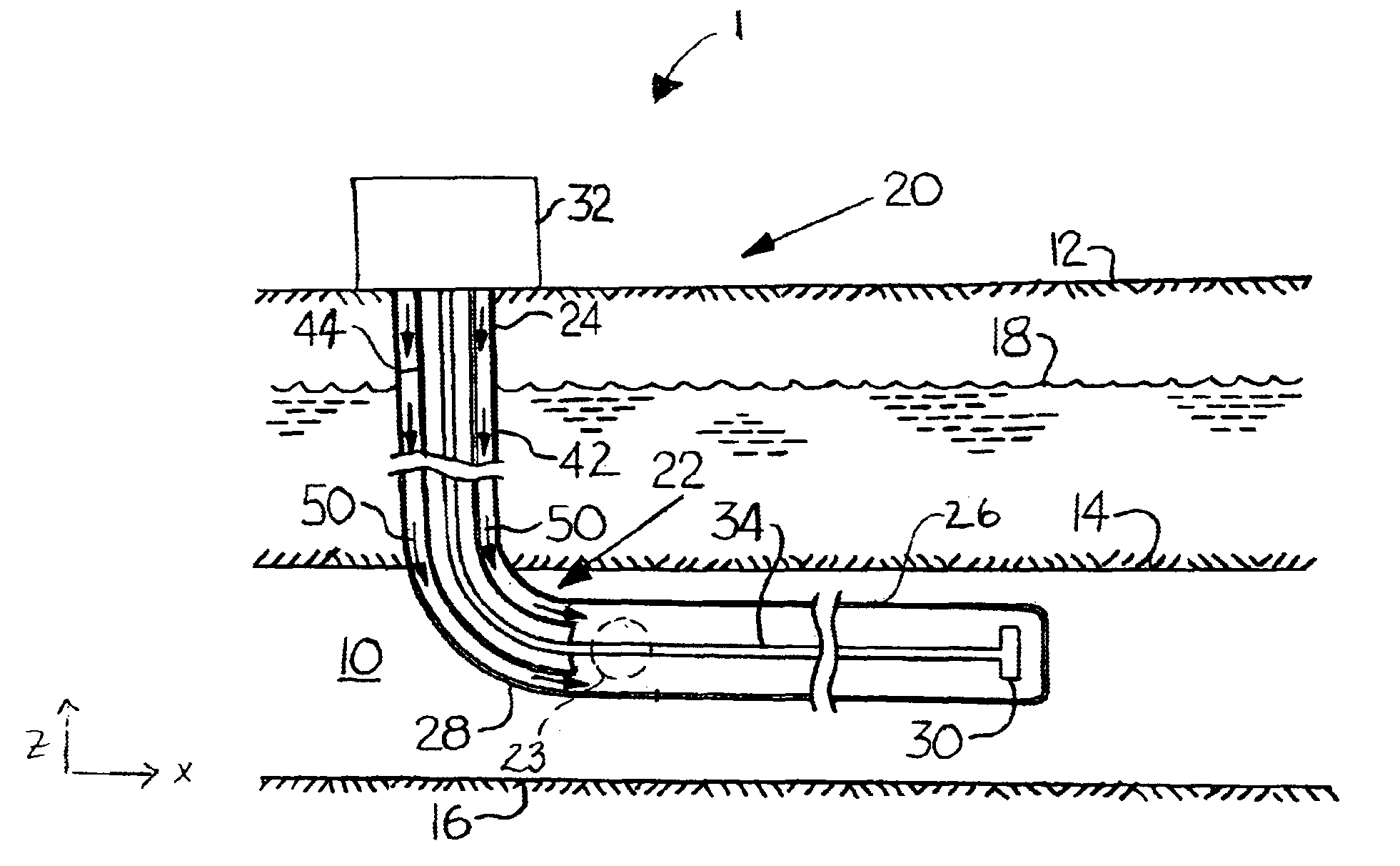
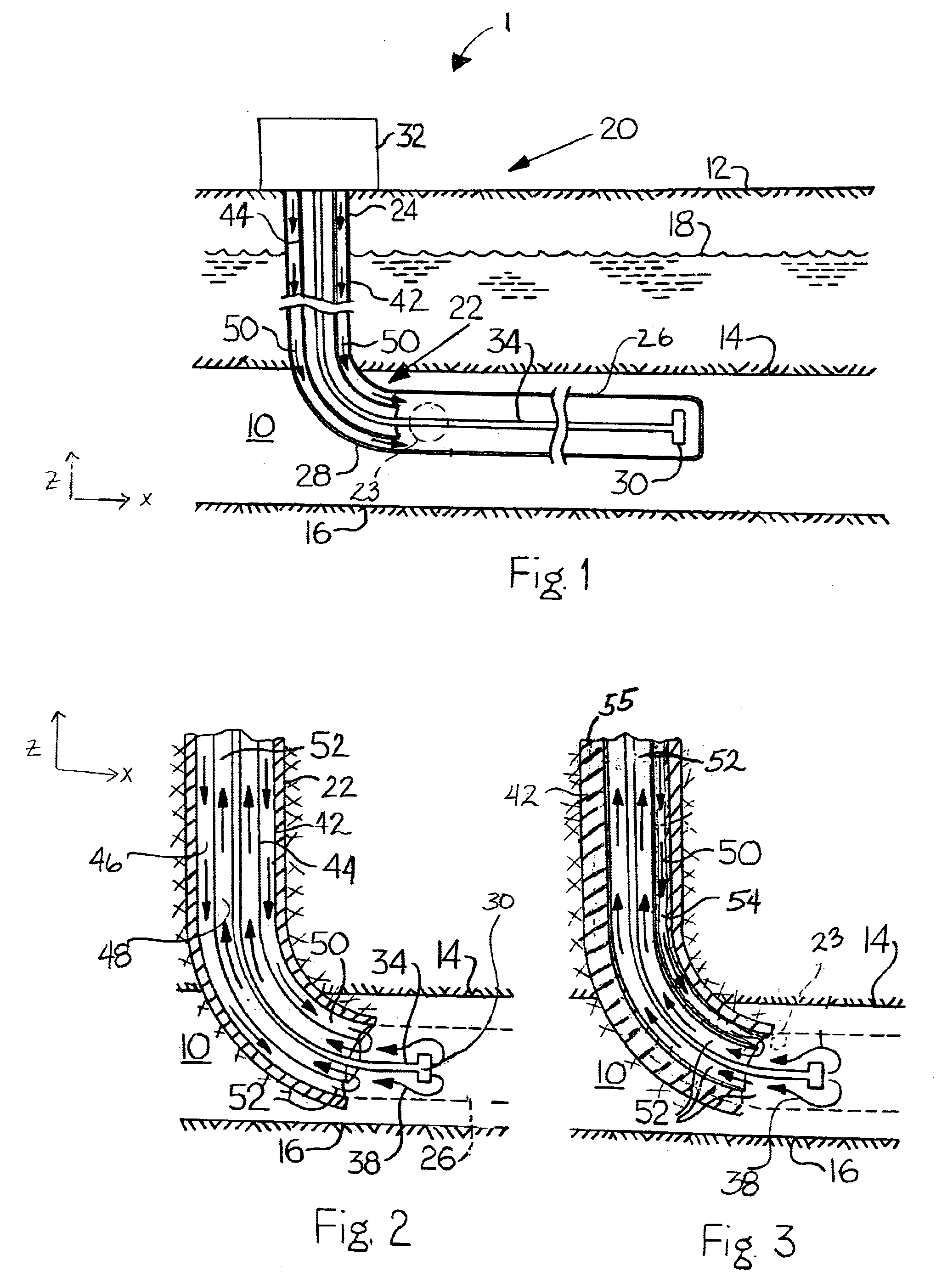
[0019]As shown in FIG. 1, th...


PUM


Abstract

A method for producing gas and water during and after drilling from a subterranean coal seam, including the steps of: (a) drilling a main bore intersecting the coal seam, the main bore having an upper substantially vertical portion, a lower substantially horizontal portion or portions, and a curved portion connecting the vertical and horizontal portions; (b) drilling one sumphole drainage bore exiting the curve or horizontal portion of the main bore and extending in the direction at least partially vertically and downwardly with respect to the horizontal portion of the main bore; (c) collecting gas produced from the coal seam through the main bore and branched bores; (d) removing water and effluent from the main bore both during drilling operations and afterwards through the use of parallel casing, whereby a first casing introduces compressed air or gas to the main bore and the annular space between the first and second casing is used for return of the mixture of water, effluent and air or gas to the surface; and (e) enhancing gas production by simultaneously removing effluent and water from the main bore by utilizing gas lifting or dewatering pumps in the drainage bore after drilling completion. The system includes a directional drilling system having a drill mechanism for cutting an object area of the coal seam, and a drill string connected to the drill mechanism to power and control. The system also includes using two casings or one casing and a compressed air tubing to air lift waste material during drilling and a dewatering device(s) installed in the sumphole drainage bore used to dewater the main bore after drilling completion.

Description

[0001]This application claims benefit of U.S. Provisional Patent Application No. 60 / 369,683, filed Apr. 3, 2002, which is incorporated herein by reference.BACKGROUND OF THE INVENTION[0002]1. Field of the Invention[0003]2. Background of the Invention[0004]Coal is a large energy source. It has been mined from the earth for many years. Deposits of coal beneath the ground surface are positioned in generally horizontal coal seams and include substantial quantities of methane gas entrained in the coal deposits. In underground coal mining, methane gas poses a significant safety risk to the miners. In the past, the methane gas entrained in the coal deposits was simply liberated from the coal, mixed with air in the mine which diluted it to a safe concentration, and the mixture was ventilated to the outside environment. The methane was simply dissipated into the environment and provided no meaningful resource. However, in recent years, this entrained methane gas has been sold commercially as ...

Claims


Application Information

Patent Timeline
Patent Type & Authority Patents(United States)
IPC IPC(8): E21B21/16E21B43/00E21B43/30E21B43/38
CPCE21B21/16E21B43/006E21B43/305E21B43/385
Inventor RUSBY, BRUCE D.WOOD, JOHN K.KRAVITS, STEPHEN J.
Owner TARGET DRILLING LLC
Why Eureka
Try Eureka