Damper

a technology of adamant and a spherical body, applied in the field of spherical body, can solve the problems of difficult to reduce the number of parts, and achieve the effects of improving endurance, preventing damage to the pressure piece, and increasing the effect of the spherical body

Inactive Publication Date: 2005-11-29
NIFCO INC
View PDF10 Cites 17 Cited by
  • Summary
  • Abstract
  • Description
  • Claims
  • Application Information

AI Technical Summary

Benefits of technology

[0021]In the fourth aspect, the cover is fitted in the opening of the cylinder. The cover is provided with the through-hole where the piston rod passes through, the pressure piece for contacting the inclining part, and the spring member for urging the pressure piece toward the inclining part. With this configuration, in addition to an elastic force of the pressure piece, the U-shaped spring applies an elastic force, so that the damper effect is increased. Also, since the inclining part does not directly contact the spring member, there is no squeaking sound through a contact between metal and plastic.
[0022]The spring contacts the pressure piece and elastically deforms. Therefore, the pressure piece receives a partial load to improve endurance against a

Problems solved by technology

Further, the covering member 206 for holding the coil spring 218 is

Method used


Image

  • Damper
  • Damper
  • Damper

Examples


Embodiment Construction

[0038]Hereunder, embodiments of the present invention will be explained with reference to the accompanying drawings. A damper mechanism is provided in a glove box inside a vehicle for damping a movement of a lid of the glove box when the lid opens, so that the lid does not open rapidly.

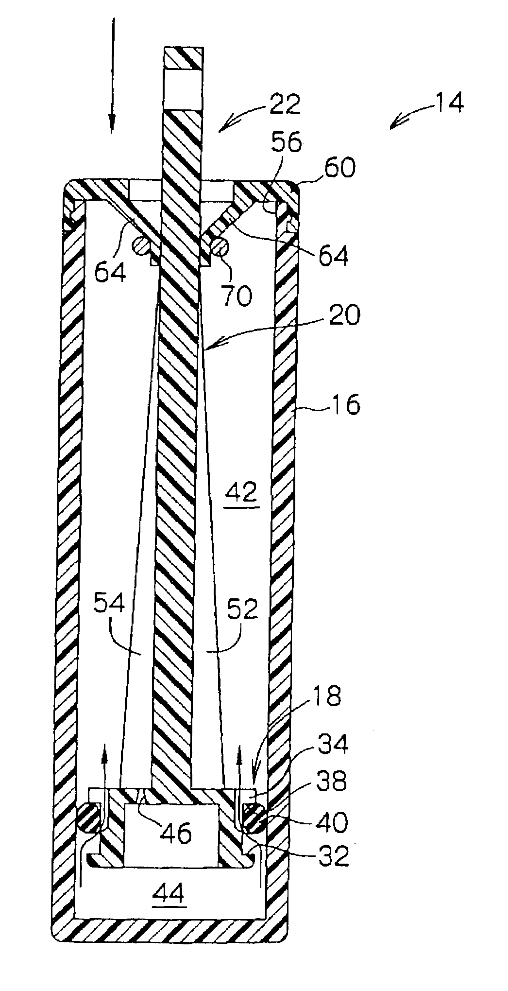
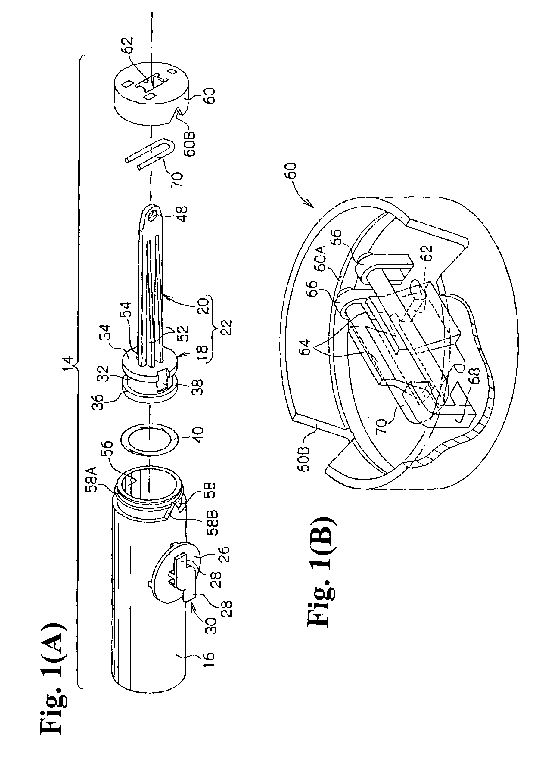
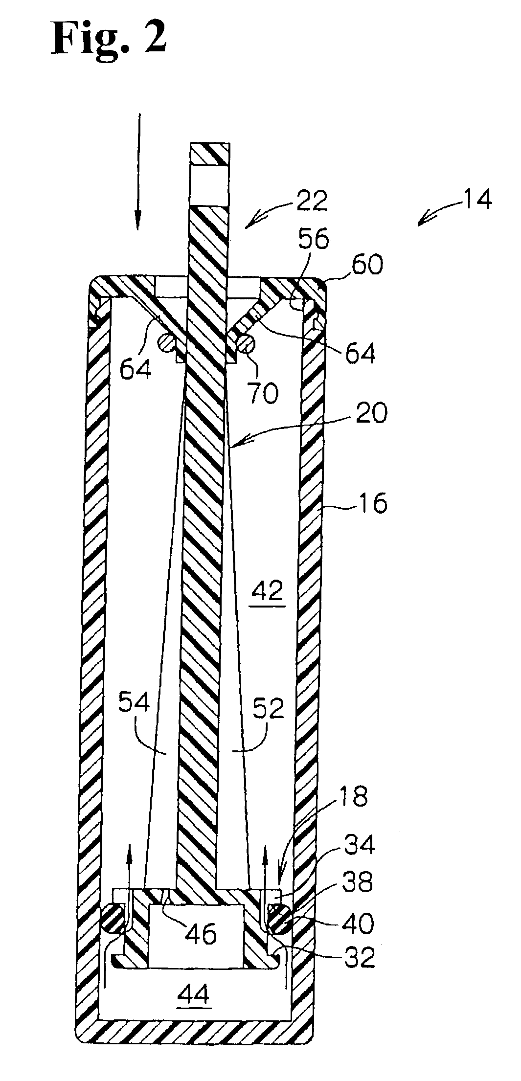
[0039]A damper according to the first embodiment of the present invention will be explained. As shown in FIG. 1(A), a damper 14 is provided with a cylinder 16 having a substantially cylindrical shape. A piston rod 22 formed of a cylindrical piston 18 and a plate-like shaft 20 as a unit is inserted to be movable in the cylinder 16.

[0040]A circular plate 26 is attached to an outer circumferential face of the cylinder 16 with a space in between. An engagement part 30 is disposed on a top face of the circular plate 26, and has engagement pieces 28 extending each other in the opposite directions with shifted centerlines.

[0041]A glove box main member 15 (refer to FIG. 4(A)) is provided with a hole (not show...


PUM


Abstract

A damper includes a cylinder, and a piston rod inserted into the cylinder through an opening portion of the cylinder. The piston rod includes front and base ends, and a frictional engaging member provided on an outer surface along a longitudinal direction thereof extending from a front end side toward the base end. A resistance device is disposed at the opening portion of the cylinder. The resistance device contacts the frictional engaging member and deforms elastically to provide frictional resistance to the piston rod as the piston rod is withdrawn from the cylinder.

Description

BACKGROUND OF THE INVENTION AND RELATED ART STATEMENT[0001]The present invention relates to a damper having a simple configuration and a compact size.[0002]A damper is used for, for example, a glove box, etc. provided inside a vehicle. When a lid of the glove box is opened, the damper controls the lid to rotate at an appropriate speed.[0003]For example, in Japanese Patent Publication (Tokkai) No. 2002-5213, a damper 200 shown in FIG. 11 includes a cylinder 202 with an open end. A cover member 206 having a through-hole 204 at the center thereof is fitted in the open end.[0004]A piston rod 212 formed of a piston 208 and a shaft 210 is placed in the cylinder 202, and is able to move along an axis direction of the cylinder 202. The piston rod 212 is disposed on an axis same as that of the cylinder 202, and has a length so that an end part of the shaft 210 is exposed from the cylinder 202 through the through-hole 204 when the piston 208 is situated at a bottom of the cylinder 202. The en...

Claims


Application Information

Patent Timeline
IPC IPC(8): F16F7/09F16F9/00F16F9/32
CPCF16F7/09F16F9/3235F16F9/3221
Inventor SHIBAO, MASAHARU
Owner NIFCO INC
Why Eureka
Try Eureka