

Exhaust gas filtering system having particulate filter for internal combustion engine
a technology of exhaust gas and particulate filter, which is applied in the direction of auxillary pretreatment, electrical control, separation processes, etc., can solve the problems of excessive dpf temperature increase, damage to dpf, and increased pressure loss, so as to effectively prevent the occurrence of rapid combustion of collected particulates
- Summary
- Abstract
- Description
- Claims
- Application Information
AI Technical Summary
Benefits of technology
Problems solved by technology
Method used
Image

Examples
third embodiment
(Third Embodiment)
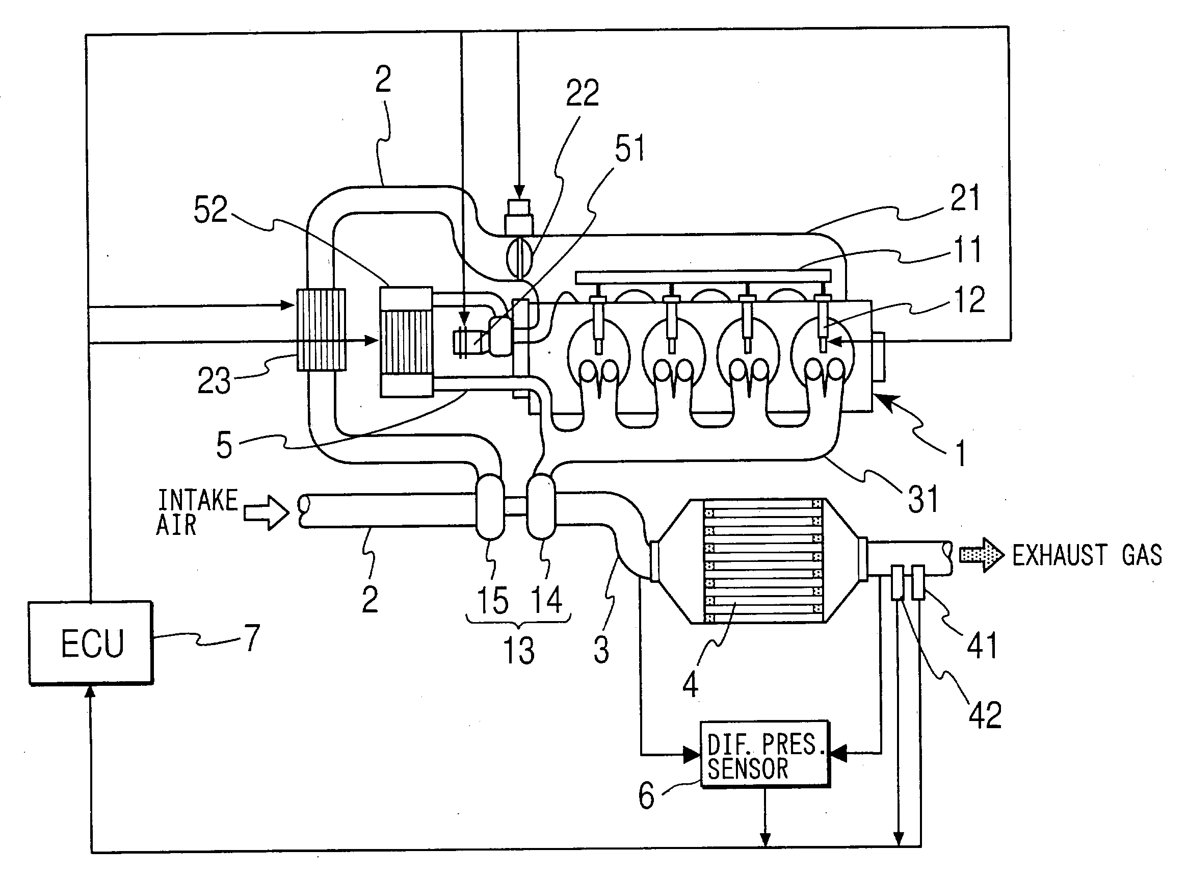
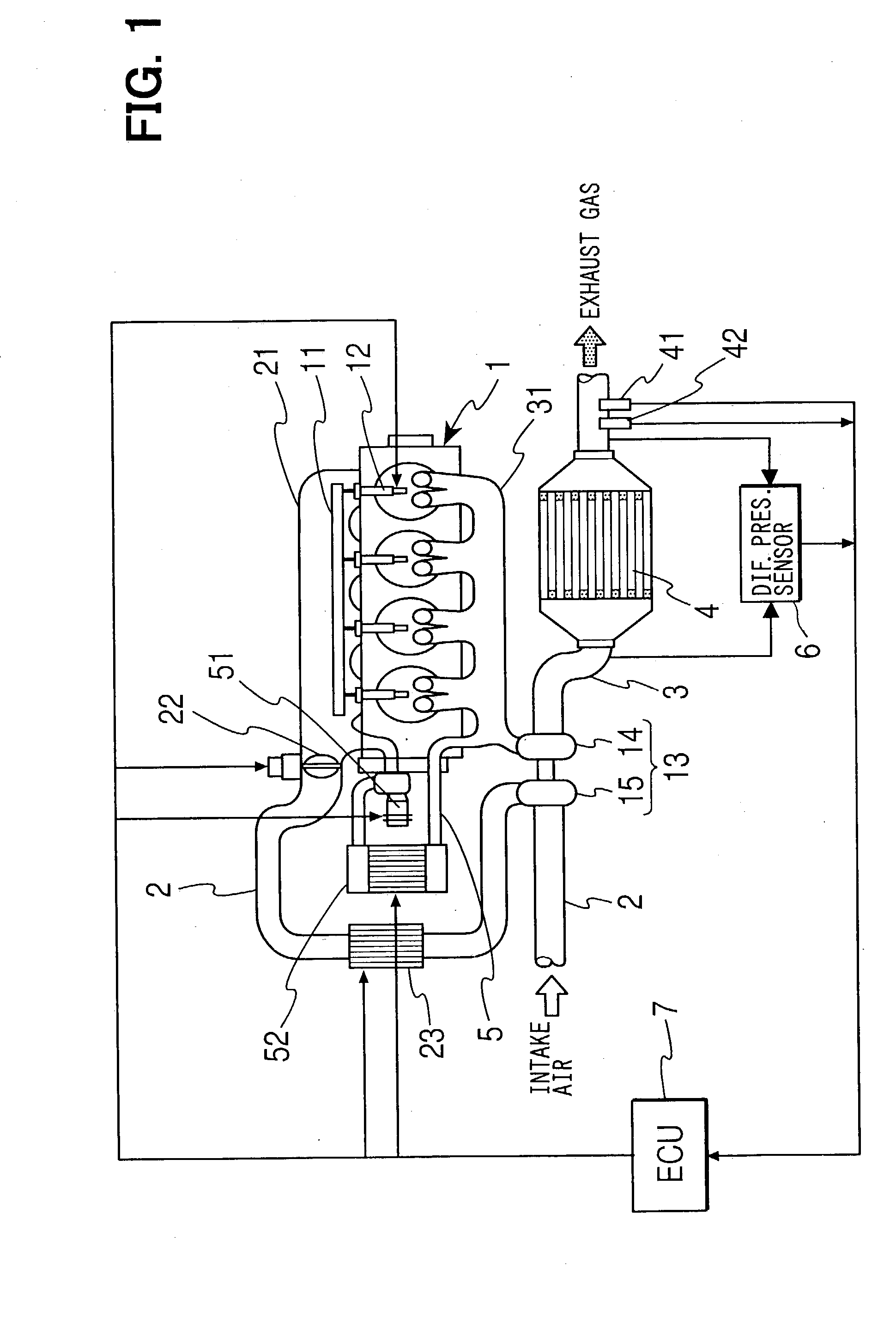
[0058]A third embodiment of the present invention will be described with reference to FIG. 7. FIG. 7 shows another type of control operation (step 103) for increasing the flow rate of gas supplied to the DPF 4 according to the third embodiment. A structure of an exhaust gas filtering system according to the third embodiment is substantially the same as that of FIG. 1 except a compressor (air supplying means) 8, which is connected to the exhaust pipe 3 at the position upstream of the DPF 4 to provide compressed air to the DPF 4 from the upstream side of the DPF 4. The compressor 8 is controlled by the ECU 7 to supply compressed air to the DPF 4 at predetermined timing. The flow rate of gas supplied to the DPF 4 is increased by the amount that corresponds to the amount of compressed air supplied to the DPF 4 from the compressor 8, so that the temperature of the DPF 4 can be advantageously reduced.
[0059]Although the gas flow rate increasing means for increasing the fl...
fourth embodiment
(Fourth Embodiment)
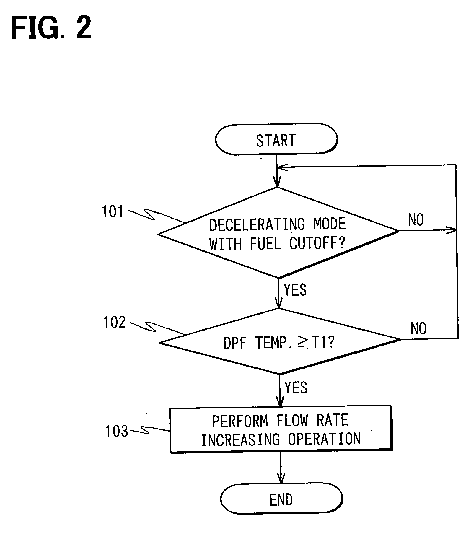
[0060]A fourth embodiment of the present invention will be described with reference to FIG. 8. A structure of an exhaust gas filtering system according to the fourth embodiment is substantially the same as that of the first embodiment and thus will not be depicted. In the present embodiment, the flow rate increasing control operation for increasing the flow rate of gas supplied to the DPF 4 is performed when the following conditions are all satisfied:
[0061]based on the operating state of the engine 1 detected by the ECU 7, it is determined that rapid combustion of the collected particulates, which are collected by the DPF 4, is likely to occur;
[0062]the temperature of the DPF 4 is equal to or greater than the threshold value T1; and
[0063]the collected particulate amount is equal to or greater than a corresponding combustible state threshold value A1.
[0064]A flow chart of the above operation performed by the ECU 7 will be described with reference to FIG. 8. First, ...
fifth embodiment
(Fifth Embodiment)
[0066]A fifth embodiment of the present invention will be described with reference to FIG. 9. A structure of an exhaust gas filtering system according to the fifth embodiment is substantially the same as that of the first embodiment and thus will not be depicted. In the present embodiment, the flow rate increasing control operation for increasing the flow rate of gas supplied to the DPF 4 is performed when the following conditions are all satisfied:
[0067]based on the operating state of the engine 1 detected by the ECU 7, it is determined that rapid combustion of the collected particulates, which are collected by the DPF 4, is likely to occur;
[0068]the temperature of the DPF 4 is equal to or greater than the threshold value T1; and
[0069]a total driving distance of the vehicle since the end of the last regeneration of the DPF 4 by the regenerating means is equal to or greater than a corresponding combustible state threshold value D1.
[0070]A flow chart of the above op...
PUM
| Property | Measurement | Unit |
|---|---|---|
| Temperature | aaaaa | aaaaa |
| Flow rate | aaaaa | aaaaa |
| Concentration | aaaaa | aaaaa |
Abstract
Description
Claims
Application Information