Method and device for manufacturing belt material for tire

a belt material and tire technology, applied in the field of tire belt material manufacturing method and device, can solve the problems of large machine not being able to manufacture multiple inability of a single machine to manufacture two types of belt materials, and inability to reduce installation space, so as to reduce manufacturing costs and reduce installation spa

Inactive Publication Date: 2005-11-29
FUJISEIKO
View PDF27 Cites 12 Cited by
  • Summary
  • Abstract
  • Description
  • Claims
  • Application Information

AI Technical Summary

Benefits of technology

[0010]It is a principal object of the present invention to provide a method and a device for manufacturing a belt material for a tire which are capable of significantly reducing a

Problems solved by technology

While these belts have been manufactured by a large machine provided with a calender, a bias cutter and the like, such a large machine is not suitable for manufacturing numerous types of belts different in specifications these days when the policy of manufacturing many kinds in small volumes is prevailing in the manufacturing industry.
Thus, a wide space is required for installing a krill mounted with a large number of bobbins, thereby giving rise to a problem that the installation space cannot be reduced.
Also, since the linear cords are arranged in a single direction, the conventional manufacturing method has a problem that difficulties are found in applying this method to the manufacturing of a belt of a two-layer structure comprising steel cords as mentioned above.
This also causes a problem in the inability of a single machine to manufacture two types of belt materials which are different in the direction in which linear cords are arranged on the radially outer side and radially inner side, and in width.
However, since the mass production system involves manufacturing large s

Method used


Image

  • Method and device for manufacturing belt material for tire
  • Method and device for manufacturing belt material for tire
  • Method and device for manufacturing belt material for tire

Examples


embodiment

(Effects of Embodiment)

[0136]Effects expected by the foregoing embodiment will be described below.

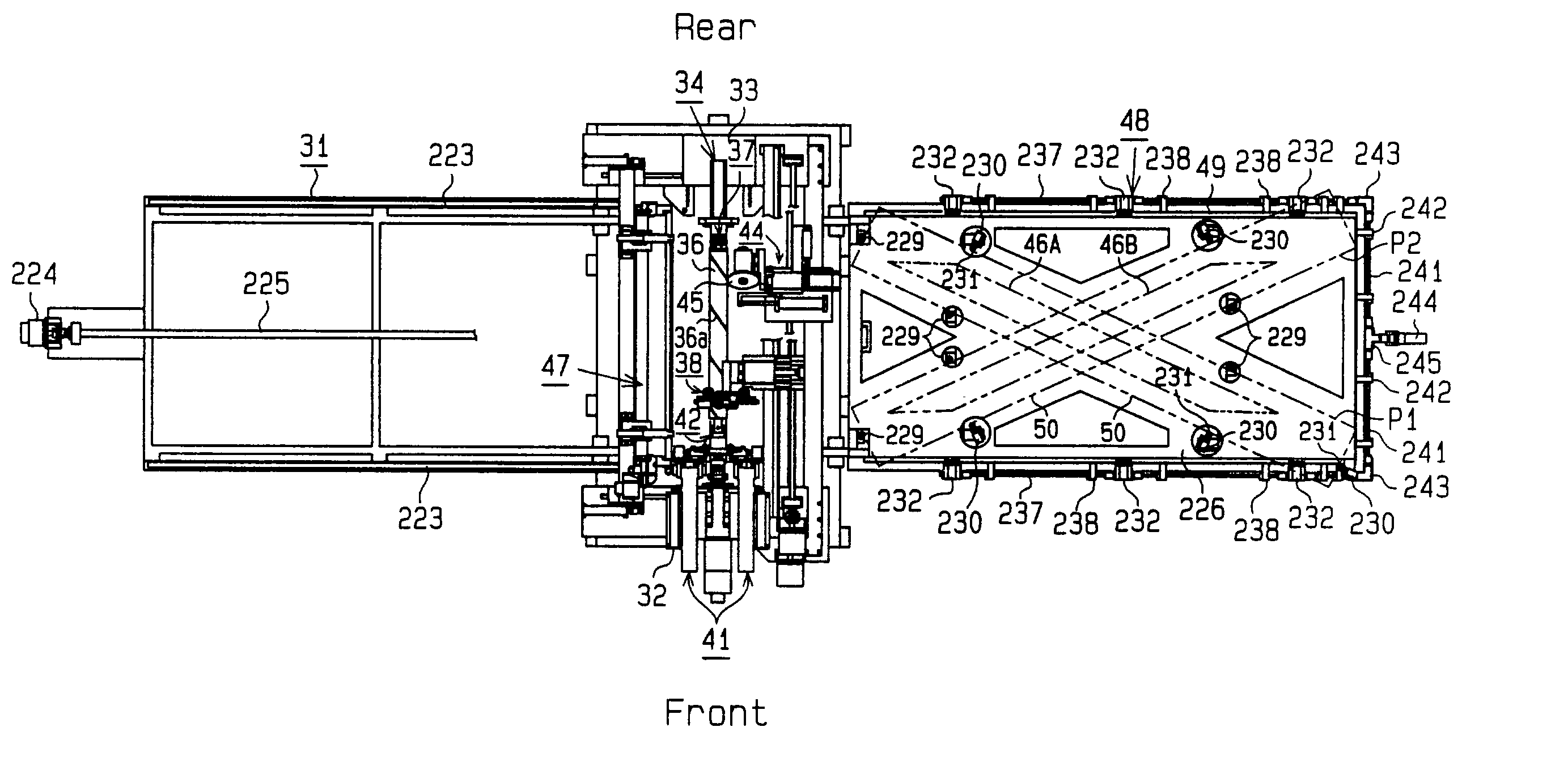
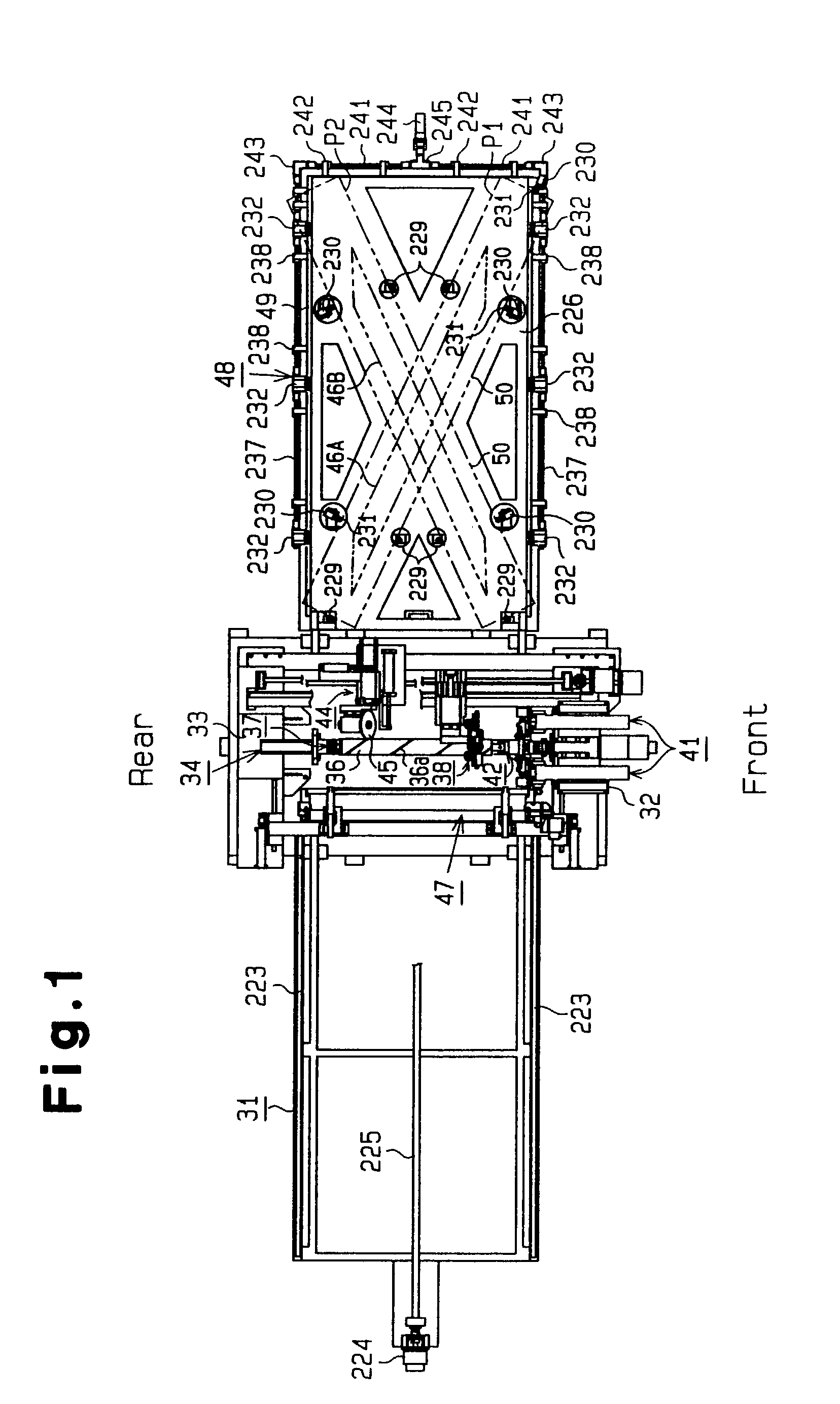
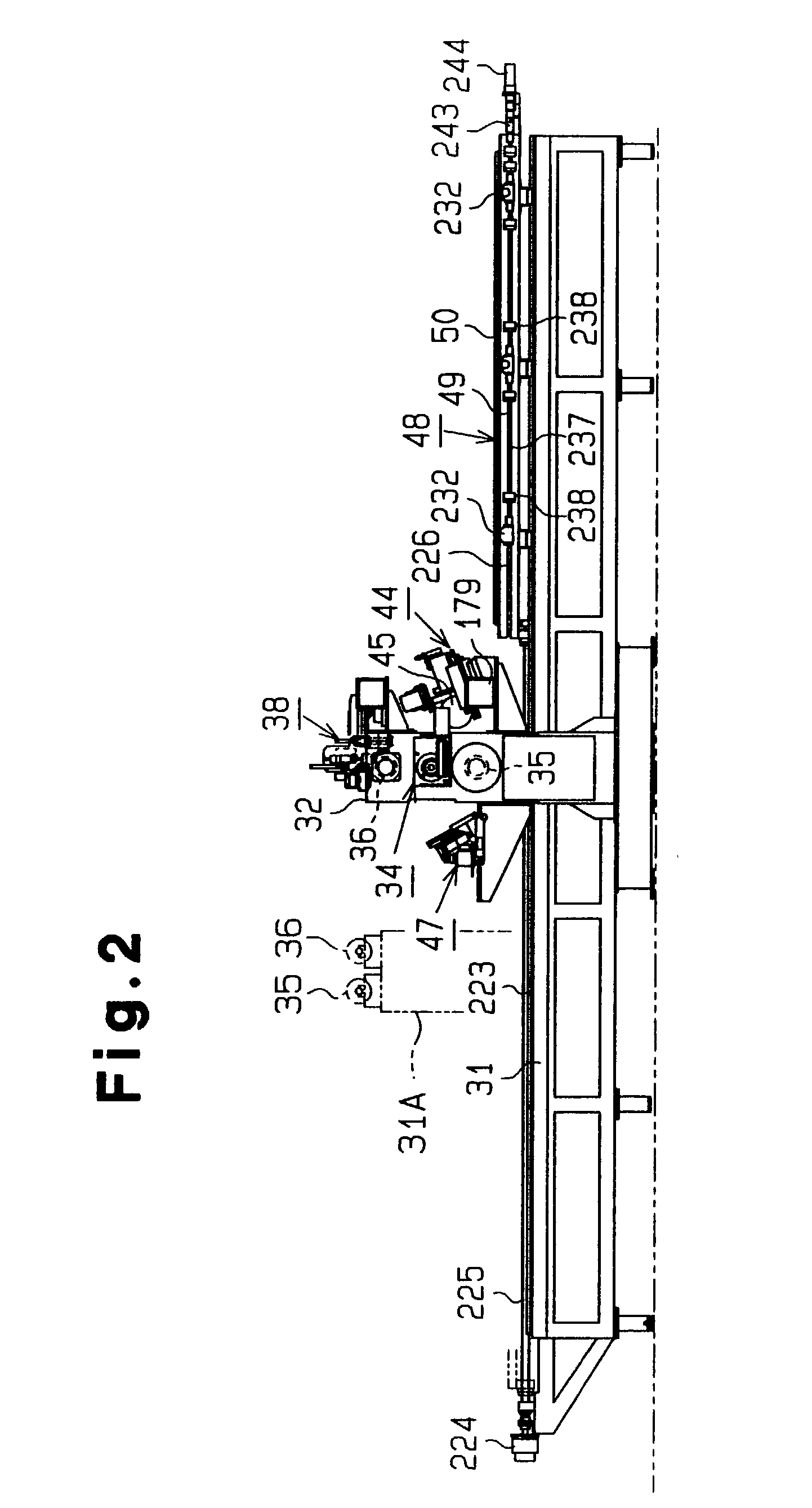
[0137](1) The ribbon 39 formed of a plurality of cords 39a arranged longitudinally and covered with the rubber 39b is spirally wound around the outer peripheral surfaces of the drums 35, 36 at predetermined pitches T1, T3. The side edges of the wound ribbon 39 are stuck to each other to form the cylindrical wound bodies 40. The wound bodies 40 are spirally cut at predetermined pitches T2, T4, larger than the winding pitches T1, T3 of the ribbon 39 to form the belt materials 46A, 46B which have the predetermined widths W1, W2, and different cord inclination angles β1, β2 in different arrangement directions. Thus, a space for installing the device for manufacturing the belt materials can be reduced.

[0138](2) The outer diameters D1, D2 of the drums 35, 36, and the width E, winding pitches T1, T3 and number N of windings of the ribbon 39, and the spiral cutting pitches T2, T4 of the wound b...


PUM

PropertyMeasurementUnit
Lengthaaaaaaaaaa
Pressureaaaaaaaaaa
Angleaaaaaaaaaa

Abstract

A method of manufacturing a belt material for tire, comprising the steps of spirally winding a ribbon, having a plurality of linear cords disposed longitudinally and coated with rubber, on the outer peripheral surface of a drum at specified pitches while the drum is rotated, sticking the side edges of the wound ribbon to each other so as to form a cylindrical wound body, and a linearly moving rotating blade in the axial direction of the drum in contact with a spiral blade groove formed in the drum at specified pitches while the drum is rotated so as to cut the wound body spirally so as to form a belt material having a specified width and a cord inclination angle.

Description

BACKGROUND OF THE INVENTION[0001]This invention relates to a method and a device for manufacturing a belt material for a tire, which is embedded and used, for example, in a pneumatic radial tire.[0002]A pneumatic tire is provided with belts on the radially outer side of a carcass layer to wrap around the carcass layer for improving the cut resistance. While these belts have been manufactured by a large machine provided with a calender, a bias cutter and the like, such a large machine is not suitable for manufacturing numerous types of belts different in specifications these days when the policy of manufacturing many kinds in small volumes is prevailing in the manufacturing industry.[0003]To address the problem as mentioned, a method of manufacturing a flat ribbon-shaped object has conventionally been proposed, for example, as disclosed in Japanese Patent Publication No. Sho 28-3485. This conventional manufacturing method involves winding back yarns from a large number of bobbins mou...

Claims


Application Information

Patent Timeline
IPC IPC(8): B26D1/00D07B1/16B26D1/18B26D3/16B26D7/26B29C53/58B29C53/66B29C53/80B29C69/00B29D30/38B29D30/46B29D30/70
CPCB26D1/185B26D3/003B26D3/162B26D7/2635B29C53/8016B29C69/003B29D30/3028B29D30/38B29D30/46B29D30/70B29C53/58B29C53/66B29C53/8091B29C2793/00B29D2030/385B29D2030/386B29K2021/00B29K2105/101B29K2105/246
Inventor TAKAGI, SHIGEMASA
Owner FUJISEIKO
Why Eureka
Try Eureka