Programmable frequency divider

a frequency divider and programming technology, applied in the field of frequency dividers, can solve the problems that even harmonic introduction defeats the purpose of using purely differential mode signals, and conventional approaches employing counters or cascaded flip-flops may not be acceptable in every situation

Inactive Publication Date: 2005-11-29
MEDIATEK INC
View PDF18 Cites 34 Cited by
  • Summary
  • Abstract
  • Description
  • Claims
  • Application Information

AI Technical Summary

Benefits of technology

[0008]In accordance with the purpose of the invention as broadly described herein, there is provided a frequency divider configured to provide an output signal having a period equal to a period of a clock signal multiplied by a division ratio, the frequency divider comprising a plurality of edge triggered storage elements arranged in at least one loop, each of the elements having a state, and a clock input, wherein the state of each storage element is determined responsive to a transition of the clock input, the state, or the inverse thereof, of one or more previous elements in the loop, a characteristic of the division ratio, and the previous state, or the inverse thereof, of the storage element, and the output signal is derived from the state, or the inverse thereof, of at least one of the elements in the loop. In one implementation, the division ratio N which is achieved is related to the number of storage elements F by the following equation: F=N+P2

Problems solved by technology

Conventional approaches employing counters or cascaded flip-flops may not be acceptable in every situation because they are incapable of producing an output having a 50% duty cycle, no matter what the integer divide ratio, or are incapable of doing so at odd integer divide ratios. FIG. 1A illustrates a clock signal, and FIG. 1B illustrates an output signal representing a division ratio of 3 obtained from a conventional frequency divider.
For example, in integrated circuits, the introduction of even harmonics defeats the purpose of using purely differential mode signals.

Method used


Image

  • Programmable frequency divider
  • Programmable frequency divider
  • Programmable frequency divider

Examples


first embodiment

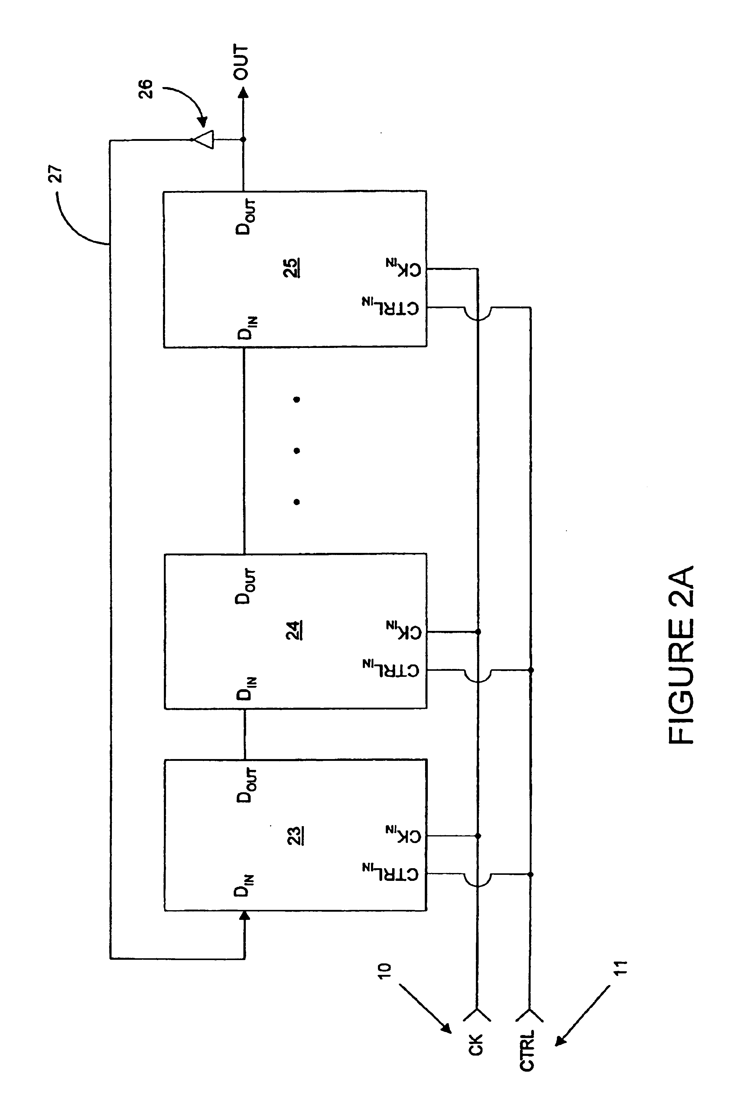
[0031]FIG. 2A illustrates the subject invention. According to this embodiment, a programmable frequency divider is provided comprising a plurality of edge triggered storage elements 23, 24, 25 arranged in sequence, each of the elements having a data input, DIN, a data output, DOUT, and a clock input, CKIN, wherein a clock signal 10 is coupled to the clock inputs of each of the storage elements, the data input of the first element in the sequence is coupled to the inverse 27 of the data output of the last element in the sequence, and the data input of each of the other elements in the sequence is coupled to the data output of the preceding element in the sequence. Each storage element is configured to trigger, i.e., change state, on either a positive or negative edge of the clock signal depending on the state of a control signal 11 indicative of a characteristic of the desired division ratio and also depending on the state of the data output DOUT of the storage element. An inverter 2...

second embodiment

[0037]the subject invention is illustrated in FIG. 2B in which, compared to FIG. 2A, like elements are referenced with like identifying numerals. In this embodiment, the division ratio N is a programmable variable, and the number F of storage elements which contributes to the frequency division function is determined responsive to the desired division ratio. This number may be less than the number of storage elements physically present in the sequence.

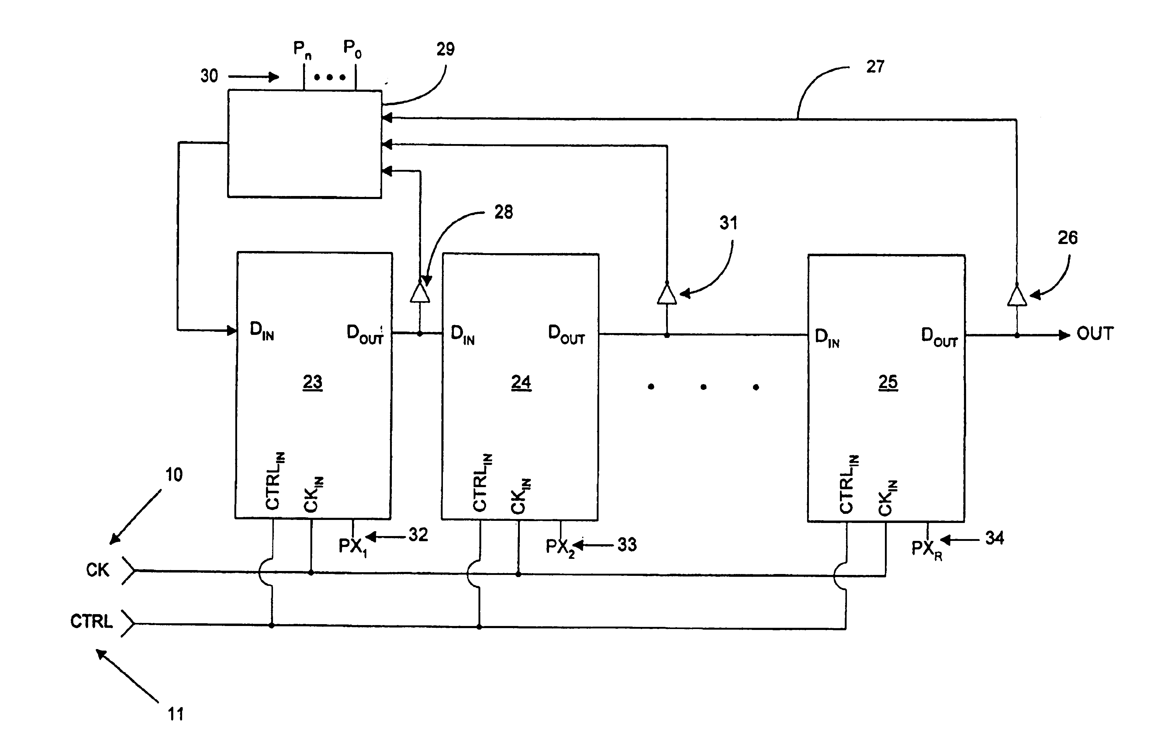
[0038]The inverse of the data outputs of each of the storage elements is provided as an input to circuit 29, the output of which is coupled to the data input of the first storage element in the sequence, storage element 23. The circuit 29 selects one of these inputs responsive to the state of control inputs P0-Pn, identified with numeral 30, and outputs the same to the data input of storage element 23. The inverse of the data outputs of storage elements 23, 24 is provided by inverters 28 and 31. (Again, in a differential mode circuit, ...

third embodiment

[0040]the subject invention is illustrated in FIG. 2C in which, compared to FIG. 2B, like elements are referenced with like identifying numerals. In this third embodiment, a power saving feature is provided in which unused storage elements in the sequence are placed in a power saving mode. Thus, in FIG. 2C, each of the storage elements 23, 24, and 25 are configured to turn off responsive to assertion of a control input PX1, PX2, PXR, respectively. These control inputs are identified in FIG. 2C with the identifying numerals 32, 33, and 34. Using these signals, the storage elements other than the F storage elements needed to participate in the frequency division operation are placed in a power saving mode.

[0041]In one implementation, each of the control and clock signal inputs to a storage element are configured as current mode signals in which a logical ‘1’ is represented through a current flow in a direction towards ground, and a logical ‘0’ is represented by the lack of such a curr...


PUM


Abstract

Various apparatus and method embodiments are disclosed. One apparatus embodiment, among others, comprises a frequency divider configured to provide an output signal having a period equal to a period of a clock signal multiplied by a programming division ratio, the frequency divider comprising a plurality of edge-triggered storage elements arranged in at least one loop, wherein each of the storage elements has a state, and a clock input, and wherein the state of each storage element is determined responsive to a transition of the clock input, the state, or the inverse thereof, of one or more previous storage elements in the loop, a characteristic of the division ratio, and the previous state, or the inverse thereof, of the storage element, and the output signal is derived from the state, or the inverse thereof, of at least one of the storage elements in the loop, a circuit for determining the number of storage elements in the loop responsive to the desired division ratio, and wherein the loop is configured such that there are odd number loop inversions within the loop, the loop inversions are implemented through inverters, and each of the storage elements is configured to enter a power save mode responsive to assertion of a power control signal.

Description

[0001]This application is a Divisional application of 09 / 370,099 filed Aug. 06, 1999, now U.S. Pat. No. 6,707,326.BACKGROUND OF THE INVENTION[0002]I. Field of the Invention[0003]This invention relates to the field of frequency dividers, and more specifically, programmable frequency dividers capable of a 50% duty cycle for odd and even integer divide ratios.[0004]II. Background of the Invention[0005]In order to provide greater flexibility in frequency planning, a competitive integrated circuit (IC)-based high frequency transceiver requires fully programmable frequency division. For example, in the receiver portion of the transceiver, a local oscillator (LO) frequency is typically a multiple of a certain reference frequency, and a programmable frequency divider is included in a phase locked loop (PLL) to generate the correct LO frequency. In the transmitter portion of the transceiver, a programmable frequency divider is typically included in the translational loop to generate the nece...

Claims


Application Information

Patent Timeline
Patent Type & Authority Patents(United States)
IPC IPC(8): H03K21/10H03K23/66
CPCG06F7/68H03K21/08H03K21/10H03K23/544H03K23/667
Inventor MAGOON, RAHULMOLNAR, ALYOSHA C.
Owner MEDIATEK INC
Why Eureka
Try Eureka