Method for defining MPEG 4 animation parameters for an animation definition interface

a definition interface and animation parameter technology, applied in the field of defining mpeg 4 animation parameters for an animation definition interface, can solve the problems of cumbersome and time-consuming, proprietary model animation is not compatible with mpeg-4 requirements, current implementation and modification of animation parameters, etc., and achieves the effect of easy and inexpensive implementation, and easy and inexpensive implementation

Inactive Publication Date: 2005-11-29
AMERICAN TELEPHONE & TELEGRAPH CO
View PDF6 Cites 4 Cited by
  • Summary
  • Abstract
  • Description
  • Claims
  • Application Information

AI Technical Summary

Benefits of technology

[0013]Another object of the present invention is to provide an animation definition interface for an MPEG renderer which can be easily and inexpensively implemented allowing for animation of arbitrary downloaded models in the MPEG-4 terminal.
[0014]It is another object of the present invention to provide an inexpensive and easily followed method for real-time animation.
[0015]The above mentioned disadvantages of prior art real-time animation with MPEG compliant renderers can be eliminated or substantially reduced by the present invention. In accordance with the invention, a method is provided that allows the rapid definition of animation parameters for proprietary models downloaded from an MPEG-4 encoder and their inclusion into proprietary real-time rendering software that might also be MPEG-4 compliant. The proprietary model can be read into any commercially available modeler. The modeler is then used to define the behavior of different animation parameters. For each animation parameter, a modified model is created and stored. Model analysis software, known as an animation definition interface, compares the original model with the animated model and extracts the essential animation parameters which represents the differences between the original and modified models. These parameters are stored in tables and are used by the real-time animation program to generate the desired expressions.

Problems solved by technology

Usually, animation of a proprietary model is not compatible with MPEG-4 requirements.
Furthermore, the current implementation and modification of animation parameters, like smiles or eyebrow movement, with these renderers is cumbersome and time consuming.

Method used


Image

  • Method for defining MPEG 4 animation parameters for an animation definition interface
  • Method for defining MPEG 4 animation parameters for an animation definition interface

Examples


Embodiment Construction

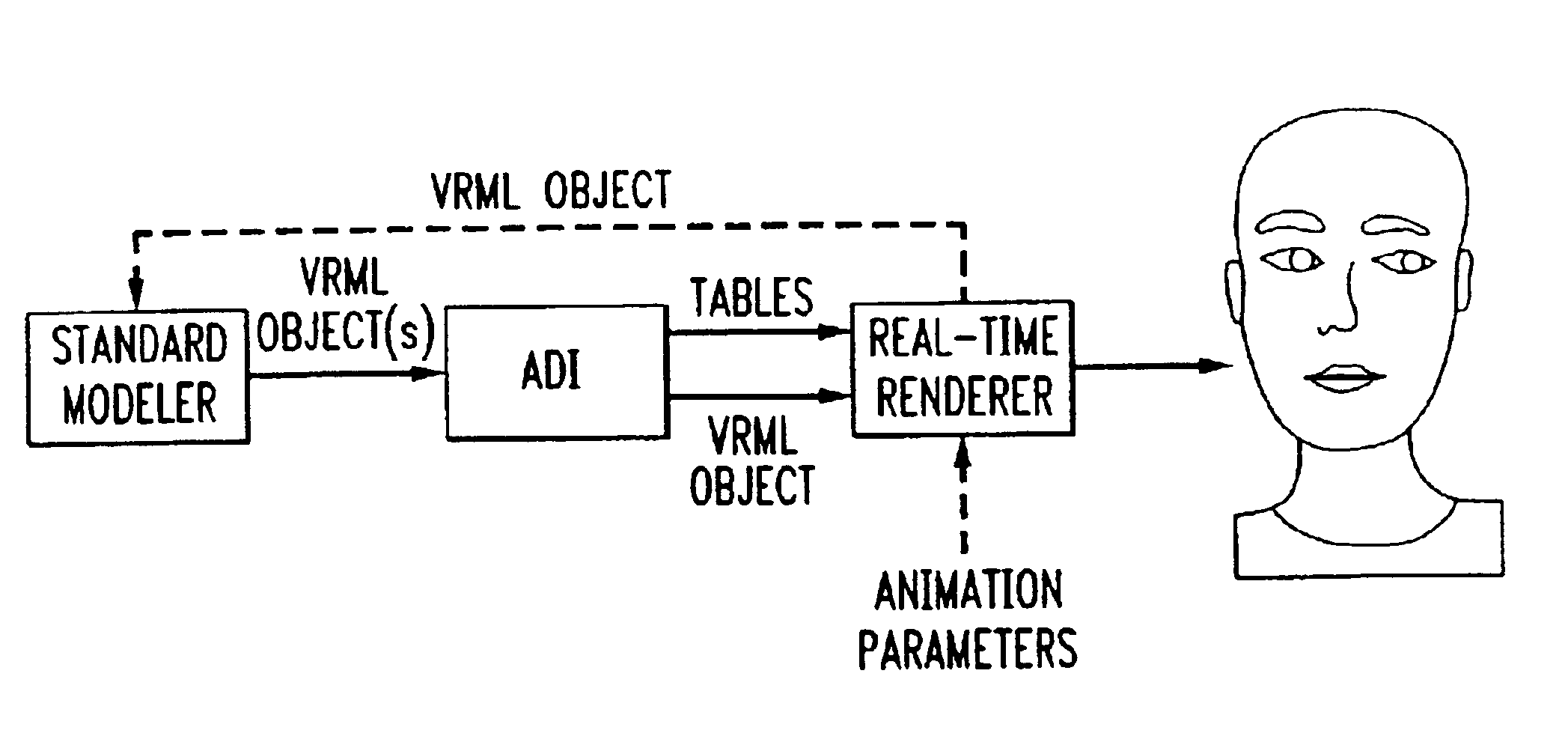
[0020]The MPEG-4 standard described above strives to define a standardized interface to allow animation of face and body models within an MPEG-4 terminal. Due to the rapid advances in computer graphics hardware, it is not foreseen that MPEG-4 will standardize face and body models. Instead, face and body definition parameters (“FDP”, “BDP”) are defined for specifying the shape and surface of a model. For the animation of the models, face and body animation parameters (“FAP”, “BAP”) are standardized.

[0021]These animation parameters include low-level parameters like “move left eyebrow up” and “tongue roll” as well as high-level parameters like “smile”. Assuming that different terminals allow for models with different degrees of complexity, a process is required that allows the rapid development of models suited for animation. The use of standardized file format like Virtual Reality Modeling Language (“VRML”) allow the use of commonly available modeling software (modelers), like COSMO 3...


PUM


Abstract

A process is defined for the rapid definition of new animation parameters for proprietary renderers. The process accommodates the peculiarities of proprietary models. In a first step, a proprietary model is animated in a standard modeler and the animated models are saved as VRML files. A converter is used to extract the meaning of a newly defined animation parameter by comparing two or more of the VRML files. Thus, the output of this process is the model and a table describing the new animation parameter. This information is read by the renderer and used whenever the animation parameter is required. The process can easily be used to generate new shapes from the original model.

Description

[0001]This application is a continuation of application Ser. No. 09 / 975,052, filed Oct. 12, 2001, now abandoned, which is a continuation of application Ser. No. 09 / 031,728, filed Feb. 27, 1998, now U.S. Pat. No. 6,154,222, issued on Nov. 28, 2000, which claims priority to U.S. Provisional Application No. 60 / 041,732, filed Mar. 27, 1997, the entire contents of which are incorporated herein by reference.[0002]This application claims priority to Provisional Application Serial No. 60 / 041,732 filed Mar. 27, 1997 and entitled “An Animation Definition Interface” and Provisional Application Serial No. 60 / 042,799 filed Apr. 7, 1997 and entitled “Let Animals And Furniture Speak: Proposal For Extending The Scope OF Face And body Animation.”[0003]The present invention generally relates to the field of computer animation and more particularly, is directed to a method for defining animation parameters for an animation definition interface.BACKGROUND OF THE INVENTION[0004]In recent years, advances...

Claims


Application Information

Patent Timeline
Patent Type & Authority Patents(United States)
IPC IPC(8): G06T9/00G06T13/00G06T15/70
CPCG06T9/001G06T13/00G06T13/40H04N21/23412H04N21/44012G06T2210/61G06T2213/04H04N19/70
Inventor HARATSCH, ERICHOSTERMANN, JOERN
Owner AMERICAN TELEPHONE & TELEGRAPH CO
Why Eureka
Try Eureka