Device for mounting a camera on a computer

a computer and camera technology, applied in the field of computer mounting, can solve the problems of limiting the user's working surface, not allowing such cameras, and providing an inferior angle from which to take images, etc., to achieve the effect of convenient use, low cost, and low cos

Inactive Publication Date: 2005-11-29
MONUMENT PEAK VENTURES LLC
View PDF6 Cites 34 Cited by
  • Summary
  • Abstract
  • Description
  • Claims
  • Application Information

AI Technical Summary

Benefits of technology

[0013]It is another purpose of the present invention to provide a tethered camera mounting device which is easy to use, removable and low cost.
[0014]It is another purpose of the present invention to provide a laptop computer camera mount that does not obscure or damage the laptop screen.
[0015]It is another purpose of the present invention to provide a device for mounting a tethered camera on a computer, which device has fewer parts than conventional devices, and which is more economical to produce.
[0016]It is another purpose of the present invention to provide a simple hinge that provides adequate torque for reliably articulating and supporting a camera relative to a holder for the camera attached to a computer.
[0017]It is still another purpose of the present invention to provide a hinge that is compact, provides moderately high frictional force, and is relatively inexpensive to produce.

Problems solved by technology

These cameras are used either in a hand-held mode, which can be inconvenient for the user or, more preferably, in a hands-free mode.
The shapes of most tethered cameras do not allow such cameras to be stably placed on a surface adjacent the computer.
These arrangements, however, may limit the user's working surface and / or provide an inferior angle from which to take the image.
Further, if the camera is on the work surface, the camera may be knocked while the computer user is trying to work, or it may be damaged in other ways, e.g., a beverage may spill on the camera.
In the laptop environment, as with a separate mouse, there may not be a convenient place to locate a stand for such a camera.
Since laptops have relatively thin, hinged screens, in comparison with the larger, box-like monitors of desktop computers, placing the stand on the laptop screen is not an option.
Further, if the laptop is actually being used on one's lap, there simply may not be a flat surface nearby on which to place the stand.
Further, and very importantly, clamp devices may stress / apply unwanted force to the screen, which could damage the screen.
Moreover, clamp-type devices may partially obscure the screen.
Also, the clamps in these devices are usually permanently and non-movably fixed to the camera, which clamps may get in the way when moving the camera.
Also, there is no separate stand available to stably hold the camera and clamp when not in use on the laptop.
Such an arrangement can be expensive to produce and service, and the camera is not available for removal and use with other computers.
Also, when such a camera is permanently attached to the laptop housing by a pivot, the amount of articulation available to the camera may be limited.
Where the camera is permanently attached to the housing by a cord, hands-free use of the camera is not possible.
Again, articulation can be limited.
Also, it is possible that, if the camera is knocked inadvertently during use, the electrical connection can be damaged.
Damage from spillage can also be of concern.
Generally, however, the hinges that are used in, e.g., laptop computers provide too much friction, are too large or are too expensive to be reliably used as a hinge for a tethered digital camera.
A plastic hinge also may experience “creep,” which is permanent deformation due to prolonged exposure to elevated temperature and or stress of the plastic materials.

Method used


Image

  • Device for mounting a camera on a computer
  • Device for mounting a camera on a computer
  • Device for mounting a camera on a computer

Examples


Embodiment Construction

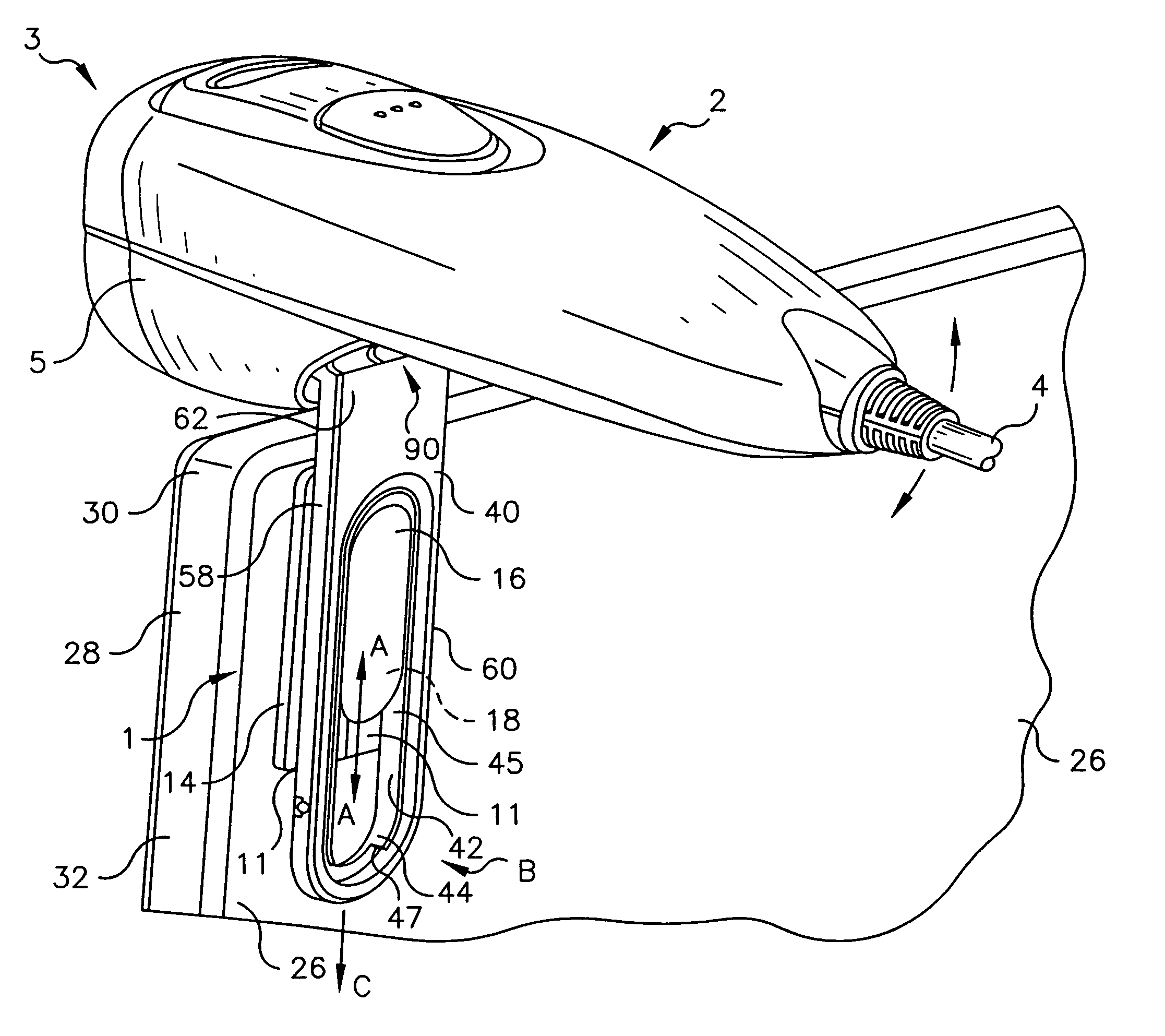
[0033]The preferred embodiments of the present invention will now be described in detail with reference to FIGS. 1–8.

[0034]The invention is a camera mounting device, referred to generally by reference numeral 1 (see FIG. 4). The device 1 includes a base or badge 10 which can be attached to a laptop screen housing via an adhesive, a holder 40 for the camera 2 that can be mated to the base 10, and a hinge 90 in the holder 40 to allow movement of the camera 2 relative to the laptop screen housing. From the camera 2 there extends a cord or tether 4 which connects to the laptop. The term “laptop” is used herein to mean a portable computing device.

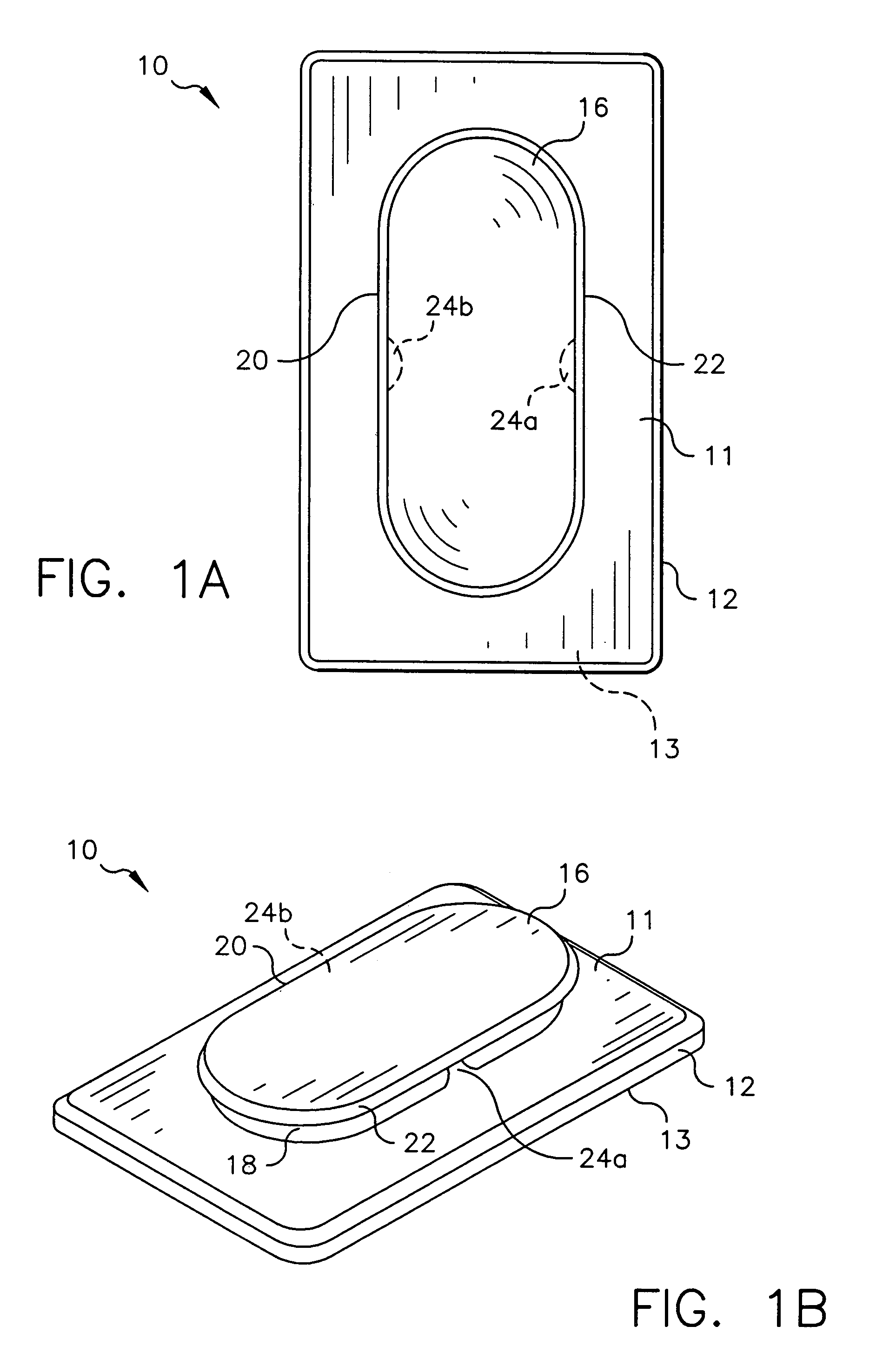
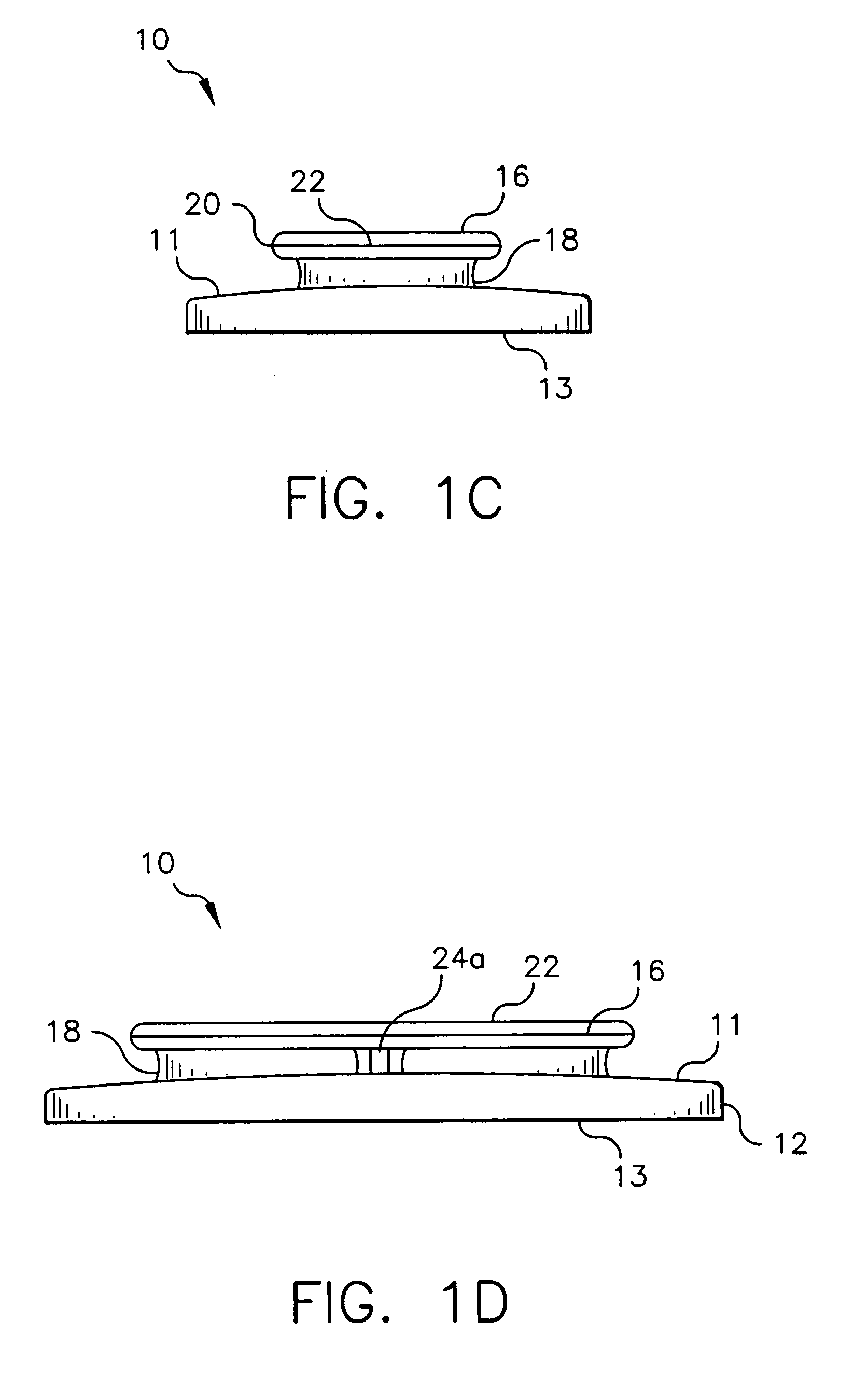
[0035]The base 10 is shown particularly in FIGS. 1A–1D, wherein FIG. 1A is a top plan view, FIG. 1B is a perspective view, FIG. 1C is a front view, and FIG. 1D is a right side view. The base 10 is preferably injection molded from plastic. As can be seen, the base 10 includes support 12 which attaches to a computer via an adhesive member 14 (see,...


PUM


Abstract

Device for mounting a tethered camera on a portable computer, including a base attached to a back of the computer's screen housing via an adhesive, a holder for the camera removably engaged to the base via cooperating mating members formed thereon, and a hinge in the holder allowing movement of the camera. The hinge includes two coil springs assembled over a pair of split shafts incorporated in the holder to provide a relatively high friction force on a pair of pins non-movably attached to the camera. The camera and holder combination can be attached to or detached from the base as need be, but the base can remain unobtrusively attached to the housing. When attached to the housing, the camera is stably held in position to allow easier hands-free use of the camera. A separate stand is also provided which can similarly mated with the holder.

Description

BACKGROUND OF THE INVENTION[0001]1. Field of the Invention[0002]This invention relates to mounting a camera on a computer and, more particularly, to a device which more reliably mounts a tethered camera on a laptop computer.[0003]2. Description of the Related Art[0004]Digital cameras are available which can, e.g., take an image of a person using a computer, and send the image to another computer for viewing. Such cameras are usually tethered, in that the camera is attached by a cord to the user's computer to allow a certain amount of mobility for the camera. See, e.g., U.S. Pat. No. 5,402,170, issued to Parulski et al., and assigned to the assignee of the present application. These cameras are used either in a hand-held mode, which can be inconvenient for the user or, more preferably, in a hands-free mode. The shapes of most tethered cameras do not allow such cameras to be stably placed on a surface adjacent the computer. Instead, a stand is usually employed to receive the camera. S...

Claims


Application Information

Patent Timeline
Patent Type & Authority Patents(United States)
IPC IPC(8): F16M13/02G06F1/16H04N5/225
CPCF16M13/02G06F1/1607F16M11/041F16M11/10F16M13/022F16M2200/041
Inventor GLOGAN, DAVID J.JOHNSON, GLENN W.AVERY, JASON M.
Owner MONUMENT PEAK VENTURES LLC
Why Eureka
Try Eureka