

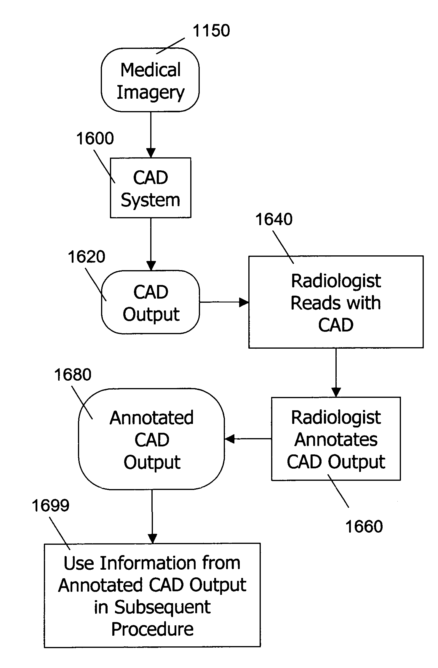
Use of computer-aided detection system outputs in clinical practice
a detection system and output technology, applied in image enhancement, image analysis, medical science, etc., can solve the problems of poor image quality, missed detection, improper patient positioning, etc., and achieve the effect of accurately and accurately locating the exact area and accurate representation of the area
- Summary
- Abstract
- Description
- Claims
- Application Information
AI Technical Summary
Benefits of technology
Problems solved by technology
Method used
Image

Examples
Embodiment Construction
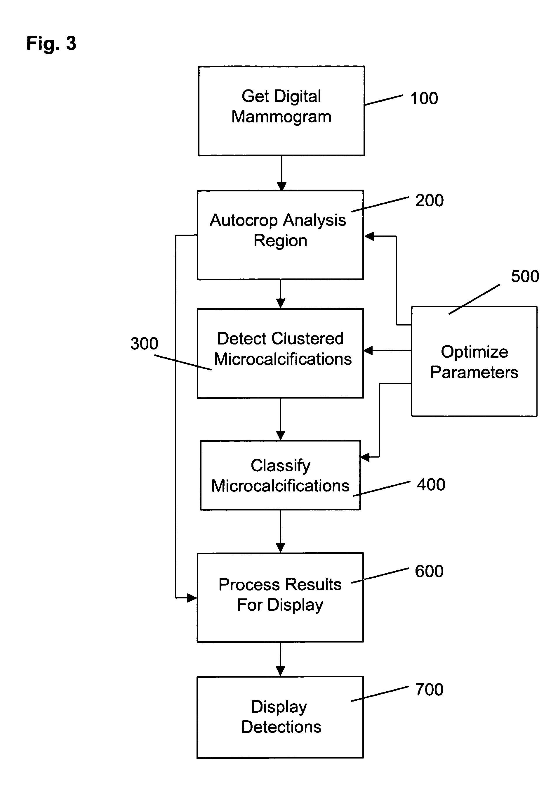
[0053]Referring now to the drawings, wherein like reference numerals designate identical or corresponding parts throughout the several views, and more particularly to FIG. 3 thereof, there is shown a flow diagram illustrating a sequence of steps performed in order to detect the locations of clusters of microcalcifications within a digital mammogram.
[0054]In a first step 100, a digital mammogram is obtained using hardware such as digital mammography systems, or by digitizing mammography films using laser or charge-coupled device (CCD) digitizers. In an optimized cropping step 200, a rectangular analysis region containing breast tissue is segmented from the digital mammogram image and a binary mask corresponding to the breast tissue is created for use in later processing steps to decrease the time required for processing the mammogram image. The binary mask is also used to limit detections to areas of the image containing breast tissue.
[0055]Clustered microcalcifications are detected ...
PUM
 Abstract
Description
Claims
Application Information