Image forming apparatus and image forming method

Inactive Publication Date: 2005-11-29
RICOH KK
View PDF19 Cites 11 Cited by
  • Summary
  • Abstract
  • Description
  • Claims
  • Application Information

AI Technical Summary

Benefits of technology

[0023]It is therefore a first object of the present invention is to provide a liquid type image forming apparatus which can control a deterioration of an image caused by a transfer failure from an intermediate transfer body to a recording body for a long time.
[0024]Present inventors have heated the intermediate transfer body having a surface layer containing a fluorine compound which deteriorates releaseability of a toner by a usage of a long processing time. Surprisingly, the releseability of the toner on the surface layer could be recovered. This is because the surface layer that the direction of the fluorine compound is disturbed by a nip pressure or a friction with a blade may be recovered to the original direction by heating.
[0025]A second purpose of the present invention is to provide an image forming apparatus and a method which can obtain a high quality image with maintaining a fine transfer performance for a long time by preventing an adhesion of a substance on the intermediate transfer body.

Problems solved by technology

However, when this powdered image is transferred by the transfer device having the intermediate transfer body, there is a problem that a filming is generated on the intermediate transfer body by the component of the powdered image.
However, in this liquid type image forming apparatus, the following problems have been left.
The liquid developer which constructs the visualized image after developing includes a large amount of the toner which is gathered as the above mentioned, while severely decreases a ratio of the carrier liquid compared to before developing because a large amount of the carrier liquid is left in the developer carrier of the developing device.
This visualized image decreases the migration performance of the toner because of reasons in which the toner becomes hard to maintain the electric charge.
Therefore, the electrostatically transferring from the intermediate transfer body to the recording body becomes difficult, and then a transfer failure is easy to be generated.
Moreover, the transfer failure is prominently generated without adopting a process, which applies pre-wet liquid on the latent image carrier before developing.
Consequently it has been difficult to prevent the transfer failure for a time.
Moreover, in the liquid developer, if the ratio of the carrier liquid is decreased, the toner becomes difficult to maintain the electric potential, so that the toner becomes hard to be migrated electrostatically.
Especially, when the liquid developer of the high viscosity and the high concentration in which the toner is dispersed into the high viscosity of the carrier liquid is used, the migration of the toner becomes harder, and the sufficient transfer performance is hard to be obtained in the secondary transfer.
If the resin in the developer is adhered onto the intermediate transfer body, and the body receives the high pressure in the secondary transfer portion, the resin may be firmly fixed for a long time.
Especially, the releaseability from the intermediate transfer body is deteriorated, and the secondary transfer performance is remarkably lowered.
Moreover, if the influence by firmly fixing the substance onto the intermediate transfer body is added, the deterioration of the secondary transfer performance is appeared prominently.

Method used


Image

  • Image forming apparatus and image forming method
  • Image forming apparatus and image forming method
  • Image forming apparatus and image forming method

Examples


first embodiment

[0101]FIG. 5 is an enlarged structural view according to the first embodiment of the printer showing one portion of the intermediate transfer roller 57 and a noncontact heating unit 9 for heating the roller. The printer is equipped with the noncontact heating unit 9 as a heating device for heating the intermediate transfer roller 57. The nonconatct heating unit 9 is disposed facing to the intermediate transfer roller 57 with a predetermined space. The noncontact heating unit 9 includes a halogen lamp, a far-infrared halogen heater, a heat source 9b such as a heating wire or the like on a platy base 9a. The noncontact heating unit 9 heats the intermediate transfer roller 57 by conducting radiation heat from the heat source to the intermediate transfer roller 57. The surface of the base 9a which is faced to the intermediate transfer roller 57 is a mirror surface finished. The heat from the heat source 9a and the reflected heat from the intermediate transfer roller 57 are thereby effec...

second embodiment

[0102]FIG. 6 is the enlarged structural view of the printer according to the second embodiment showing one portion of the intermediate transfer roller 57 and a heating belt unit for heating the roller. The printer is equipped with a heating belt unit 10 as a heating device for heating the intermediate transfer roller 57. The heating belt unit 10 includes a heating belt 11 which is composed of a heat resistance material, a driven roller 12 which is wound by the belt, a driving roller 13, a heating roller 14 and so on. The heating belt 11 is moved endlessly in the clockwise direction shown in the view at the same linear velocity with the intermediate transfer roller 57 so as to move on the surface of the roller toward the same direction with the intermediate transfer roller 57 by driving of the driving roller 13 at the contacted portion with contacting to the intermediate transfer roller 57. The heat roller 14 which includes the heat source inside is contacted onto the backside of the...

third embodiment

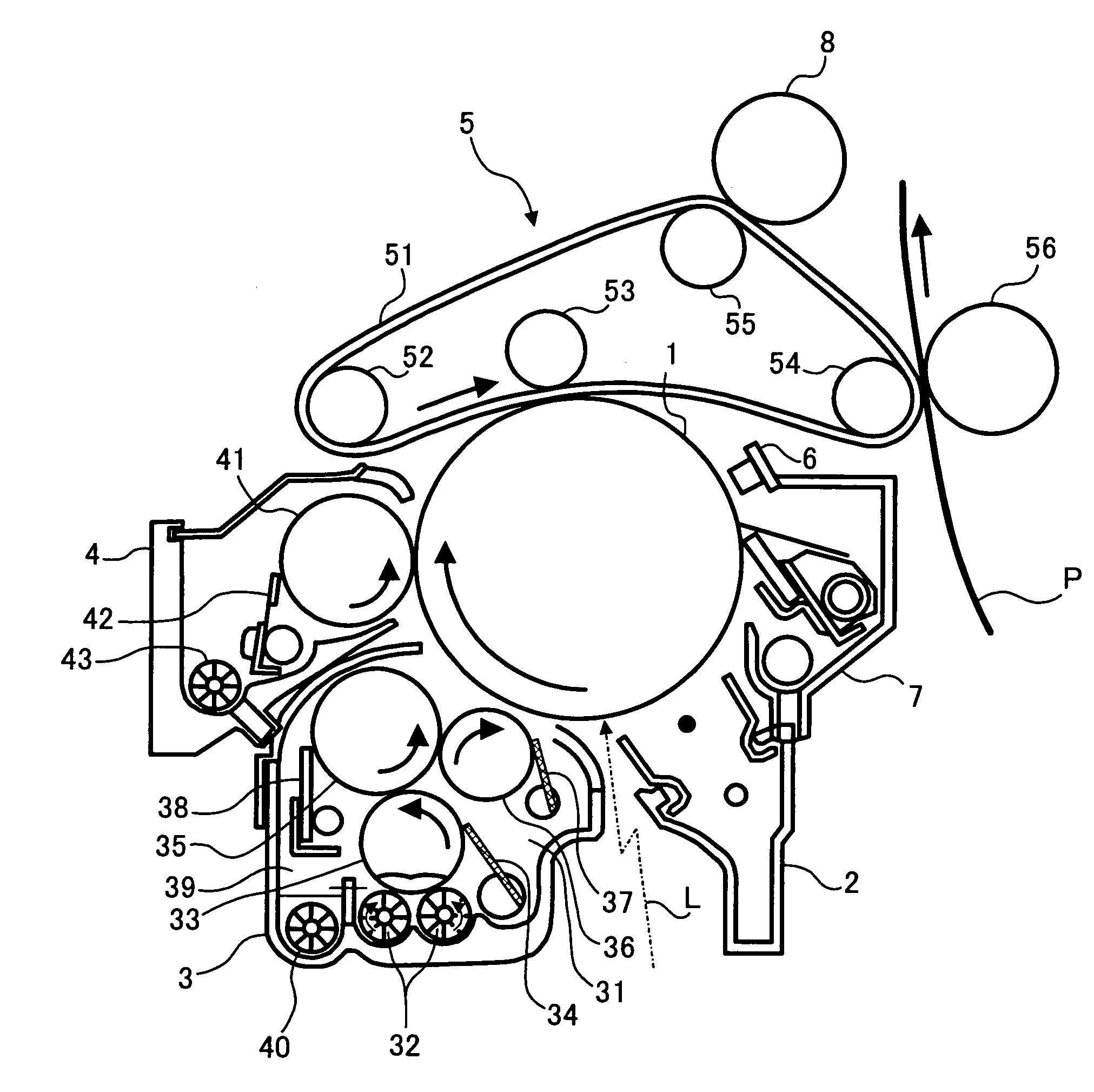
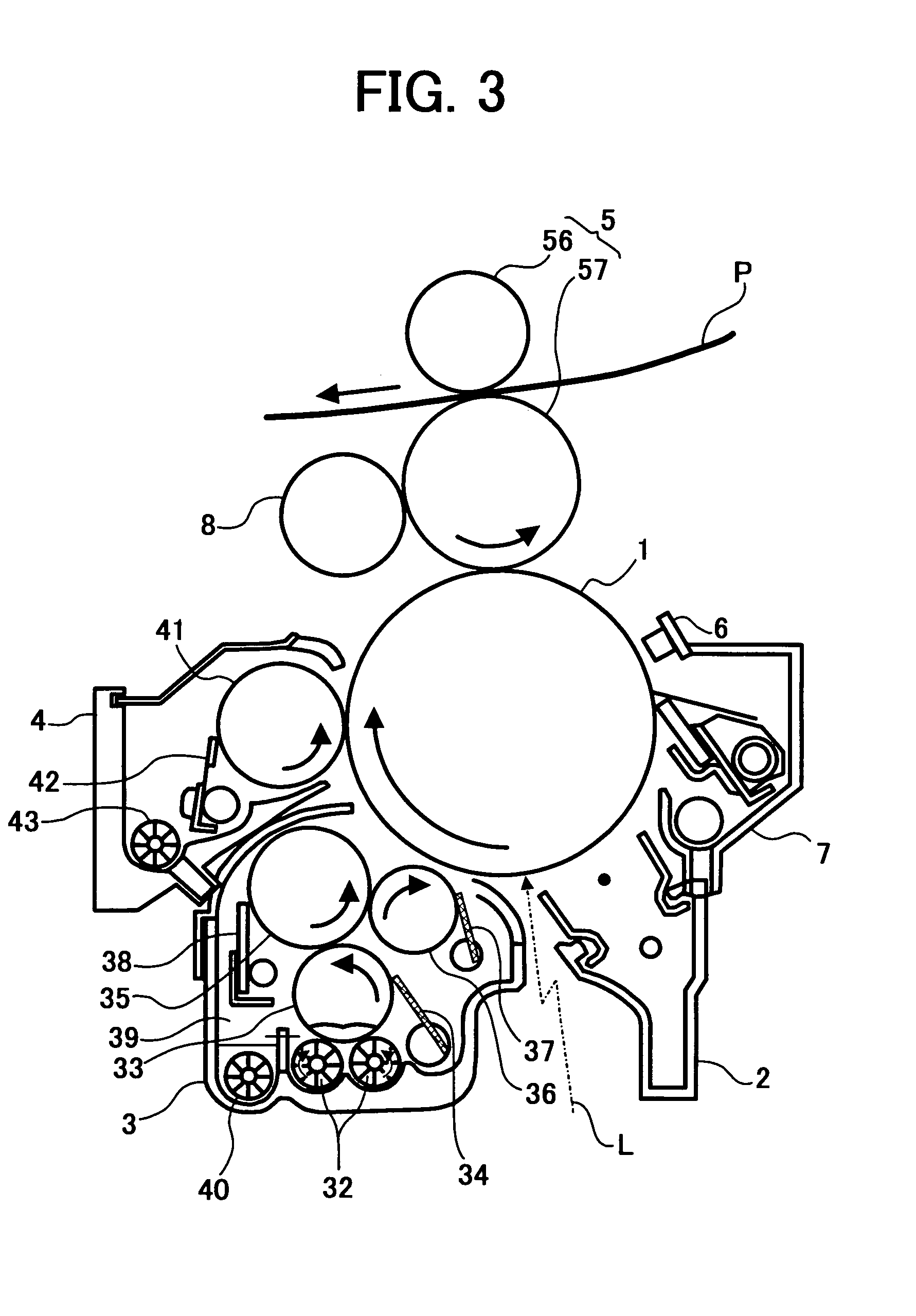
[0103]In the modification example device as shown in the FIG. 3, the secondary transfer bias roller 56 is operated as a pressing roller for pressuring the transfer paper P in which the toner image from the intermediate transfer roller 57 is transferred toward the intermediate transfer roller 57. In the printer according to the third embodiment, the heat source is disposed in the secondary transfer bias roller 56 as the pressuring roller, and the secondary transfer bias roller is also used as the heating device for the intermediate transfer roller 57. In the arrangement, the pressuring roller is also used as the heating device so that a space or the number of parts is reduced.

[0104]The printer for forming a single color toner image by using one photoconductivity and one developing unit 3 is described above. However, the present invention can be applied to a liquid type image forming apparatus for forming a color image by a following method. In other word, the method is that several d...


PUM


Abstract

A liquid type image forming apparatus includes a latent image carrier for carrying a latent image, a developing device for developing the latent image on the latent image carrier into a visualized image by a liquid developer containing a toner in a carrier liquid, and a transfer device for electrostatically transferring the visualized image on a recording body after the visualized image on the latent image carrier is intermediately transferred onto an intermediate transfer body. A fluorine compound is coated on at least a surface of the intermediate transfer body. The liquid type image forming apparatus is provided with a heating device for heating the intermediate transfer body.

Description

BACKGROUND OF THE INVENTION[0001]1. Field of the Invention[0002]The present invention relates to an image forming apparatus and an image forming method in which after a latent image on a latent image carrier is developed by liquid developer, an obtained visualized image is electrostatically transferred on a recording body through an intermediate transfer body.[0003]2. Description of the Prior Art[0004]Conventionally, a liquid type image forming apparatus which utilizes liquid developer containing a toner and carrier liquid for a development of a latent image has been well known. This liquid type image forming apparatus can utilize a far smaller diameter of a toner compared to a dry type image forming apparatus which conducts a development by a powered toner, so that the liquid type image forming apparatus can form an image which has an excellent reproducibility of dots and a high resolution.[0005]In recent years, an improved liquid type image forming apparatus has been proposed. In ...

Claims


Application Information

Patent Timeline
IPC IPC(8): G03G15/16
CPCG03G15/161G03G15/162
Inventor YOSHINO, MIESASAKI, TSUTOMU
Owner RICOH KK
Why Eureka
Try Eureka