Engine valve actuation control and method for steady state and transient operation

a technology of engine valve actuator and control method, which is applied in the direction of machines/engines, non-mechanical valves, valve arrangements, etc., can solve the problems of requiring a powerful and expensive actuator, requiring advanced control algorithms, and limiting bandwidth

Inactive Publication Date: 2005-12-06
GM GLOBAL TECH OPERATIONS LLC
View PDF5 Cites 10 Cited by
  • Summary
  • Abstract
  • Description
  • Claims
  • Application Information

AI Technical Summary

Benefits of technology

[0008]The PIDC function of the control interfaces with the spool valve actuator to adjust the position of the spool valve when the valve is at seat or maximum lift and thereby alter engine valve opening timing and the duration of the engine valve event.

Problems solved by technology

Such valve trains are often controlled with algorithms which provide limited bandwidth.
However, the traditional engine valve motion profile is cyclic but aperiodic in time domain as engine speed changes.
Some advanced control algorithms, such as repetitive control cannot be applied under speed transient conditions.
To track these profiles precisely, the engine valve actuator must have the capability of precise tracking over a continuous frequency spectrum, which usually demands a powerful and expensive actuator.
As a result, conventional controls cannot achieve satisfactory performance under speed transient conditions.

Method used


Image

  • Engine valve actuation control and method for steady state and transient operation
  • Engine valve actuation control and method for steady state and transient operation
  • Engine valve actuation control and method for steady state and transient operation

Examples


Embodiment Construction

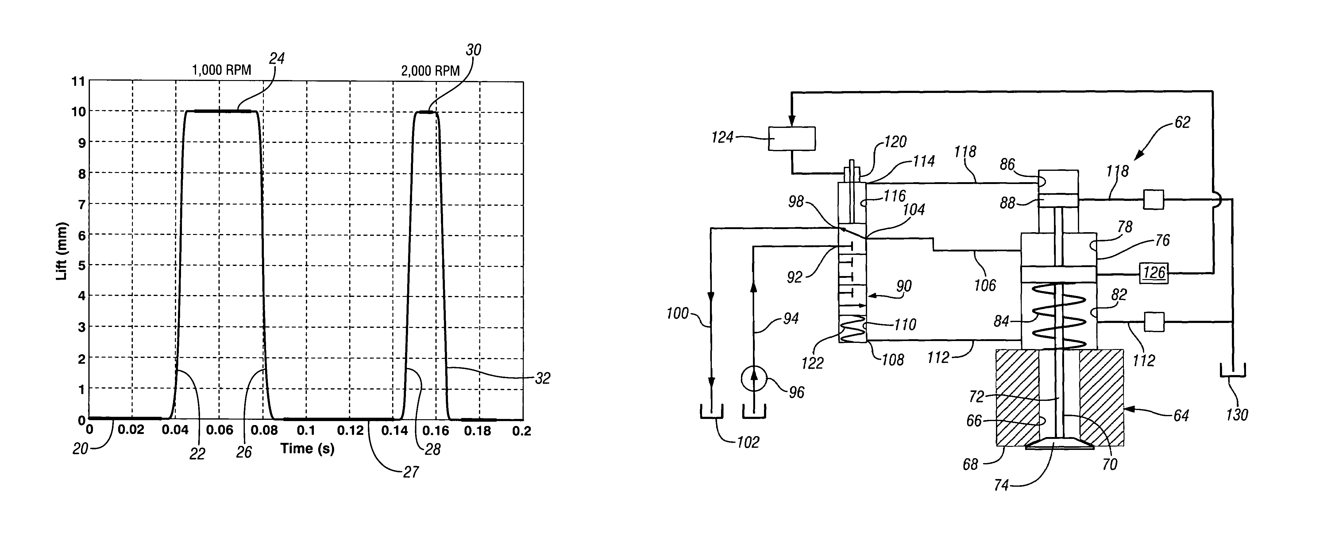
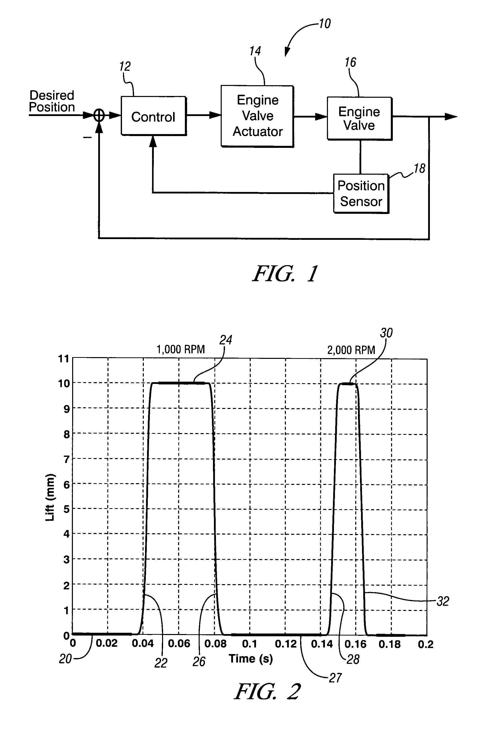
[0021]Referring first to FIG. 1 of the drawings in detail, numeral 10 generally indicates a basic outline of a control system of the present invention. The control system 10 includes a control 12 incorporating an algorithm which may be implemented by any suitable control methods, such as a repetitive control (RC) function and a proportional integral derivative control (PIDC) function or other means performing the same or similar functions. The control 12 interfaces with an engine valve actuator 14 operable to move an engine valve 16 between an open position and a closed position.

[0022]The actuator 14 may act directly on the engine valve 16 or may act indirectly on the engine valve using hydraulic channels, or mechanical means. The position of the engine valve is monitored by an engine valve position sensor 18 which relays engine valve position information to the control 12. The control energizes and de-energizes the actuator 14 to operate the engine valve 16 according to the valve m...


PUM


Abstract

A valve actuator control monitors engine speed, engine valve timing, engine valve lift dwell duration and engine valve seating velocity and varies the timing of the engine valve event by adjusting the lift dwell duration of the engine valve while keeping time invariant opening and closing profiles.

Description

CROSS-REFERENCE TO RELATED APPLICATIONS[0001]This application claims priority from U.S. Provisional Patent Application No. 60 / 589,692 filed Jul. 21, 2004.TECHNICAL FIELD[0002]This invention relates to engine valve trains and, more particularly, to a control and method for operating an engine valve actuator for an internal combustion engine.BACKGROUND OF THE INVENTION[0003]Valve actuators for camless valve trains of internal combustion engines have been proposed in the art. Such valve trains are often controlled with algorithms which provide limited bandwidth. However, the traditional engine valve motion profile is cyclic but aperiodic in time domain as engine speed changes. Some advanced control algorithms, such as repetitive control cannot be applied under speed transient conditions. To track these profiles precisely, the engine valve actuator must have the capability of precise tracking over a continuous frequency spectrum, which usually demands a powerful and expensive actuator. ...

Claims


Application Information

Patent Timeline
Patent Type & Authority Patents(United States)
IPC IPC(8): F01L9/10F01L1/34
CPCF01L9/02F01L2800/00F01L9/10
Inventor SUN, ZONGXUAN
Owner GM GLOBAL TECH OPERATIONS LLC
Why Eureka
Try Eureka