Energy recovery system for work vehicle including hydraulic drive circuit and method of recovering energy

a technology of energy recovery and work vehicle, which is applied in the direction of electric propulsion mounting, jet propulsion mounting, transportation and packaging, etc., can solve the problems of large energy consumption of vehicles such as wheel loaders and backhoes, large fuel consumption of vehicles, repeated starting and stopping,

Inactive Publication Date: 2005-12-06
BLUE LEAF I P +1
View PDF7 Cites 85 Cited by
  • Summary
  • Abstract
  • Description
  • Claims
  • Application Information

AI Technical Summary

Benefits of technology

[0015]In accordance with a first embodiment of the invention, an energy-recovering hydraulic drive system for a work vehicle is provided, including an internal combustion engine, a hydrostatic ground drive circuit, a gas-charged hydraulic accumulator and a valve assembly that is coupled to and between the accumula

Problems solved by technology

Some of these vehicles, such as wheel loaders and backhoes, engage in a great deal of start and stop motion.
One problem with these vehicles is their fuel consumption.
The repeated starting and stoppi

Method used


Image

  • Energy recovery system for work vehicle including hydraulic drive circuit and method of recovering energy
  • Energy recovery system for work vehicle including hydraulic drive circuit and method of recovering energy
  • Energy recovery system for work vehicle including hydraulic drive circuit and method of recovering energy

Examples


Embodiment Construction

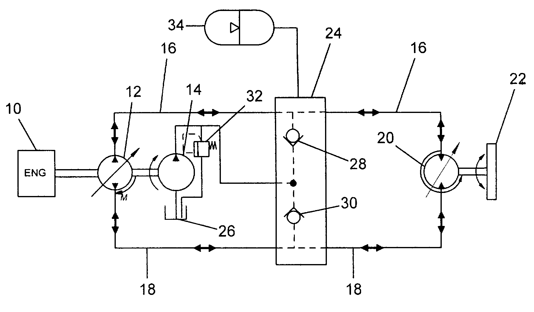
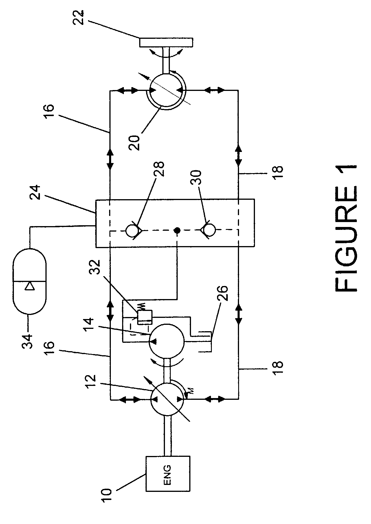
[0032]Referring to FIG. 1, a hydrostatic drive circuit is illustrated. The circuit is coupled to and driven by an engine 10, and, in turn, drives a vehicle wheel 22.

[0033]The basic elements of the drive circuit are a drive pump 12 that is fluidly coupled to drive motor 20 by two conduits 16 and 18. When engine 10 drives the drive pump 12, to which it is coupled, pump 12 produces hydraulic fluid under pressure. This pressurized fluid is conducted either into conduit 16 or conduit 18, depending upon the position of the swash plate of pump 12.

[0034]Since pump 12 provides both bidirectional and infinitely variable flow, it can direct pressurized fluid out of either port. Either port, in short can be an outlet or output port as well as an inlet or input port, depending upon the direction of pump flow. Similarly, drive motor 20 and wheel 22 rotate in either direction depending upon the direction of flow out of pump 12.

[0035]The drive circuit is hydrostatic, and contains a relatively const...


PUM


Abstract

A work vehicle having a hydrostatic drive system provides for the recovery and reuse of the vehicle's kinetic energy by conducting pressurized hydraulic fluid out of the hydrostatic drive system into an accumulator during vehicle deceleration, and conducting the pressurized fluid back into the drive system during vehicle acceleration to assist the vehicle's engine in accelerating the vehicle.

Description

FIELD OF THE INVENTION[0001]The invention relates generally to propulsion systems for work vehicles. More particularly it relates to propulsion systems that regenerate energy.BACKGROUND OF THE INVENTION[0002]Work vehicles, such as skid steer loaders, bulldozers, backhoes, wheel loaders, graders, dump truck and the like often use hydraulic propulsion systems. In these systems, an internal combustion engine is coupled to a hydraulic pump to provide a source of hydraulic fluid under pressure.[0003]The pressurized hydraulic fluid is conducted though hoses and tubing to a variety of actuators and motors to provide them with motive power. One or more of the motors may be connected to the drive wheels to drive the vehicle over the ground. Other actuator such as hydraulic cylinders may be used to move various implements or peripheral mechanisms.[0004]By using hydraulic fluid as a source of power, the prohibitive cost of complicated gears, belts, transmissions, gearboxes, etc.—all otherwise ...

Claims


Application Information

Patent Timeline
IPC IPC(8): B60K6/12E02F9/22F15B1/02F15B21/14F16H61/40F16H61/4096F16H61/4139
CPCB60K6/12E02F9/2217F15B1/024F15B21/14F16H61/4096F16H61/4139Y02T10/6208Y02T10/62
Inventor SHORE, DANIEL B.DIX, PETER J.
Owner BLUE LEAF I P
Why Eureka
Try Eureka