
Handrail-drive for an escalator or a moving walk

a technology for escalators and walking walks, applied in escalators, transportation and packaging, conveying, etc., can solve the problems of shortening the service life of the drive-wheels and the follow-wheels, exerting a high pressing force, etc., and achieves a greater contact area, reduced friction, and reduced force applied to the handrail

Active Publication Date: 2005-12-06
INVENTIO AG
View PDF6 Cites 15 Cited by
  • Summary
  • Abstract
  • Description
  • Claims
  • Application Information

AI Technical Summary

Benefits of technology

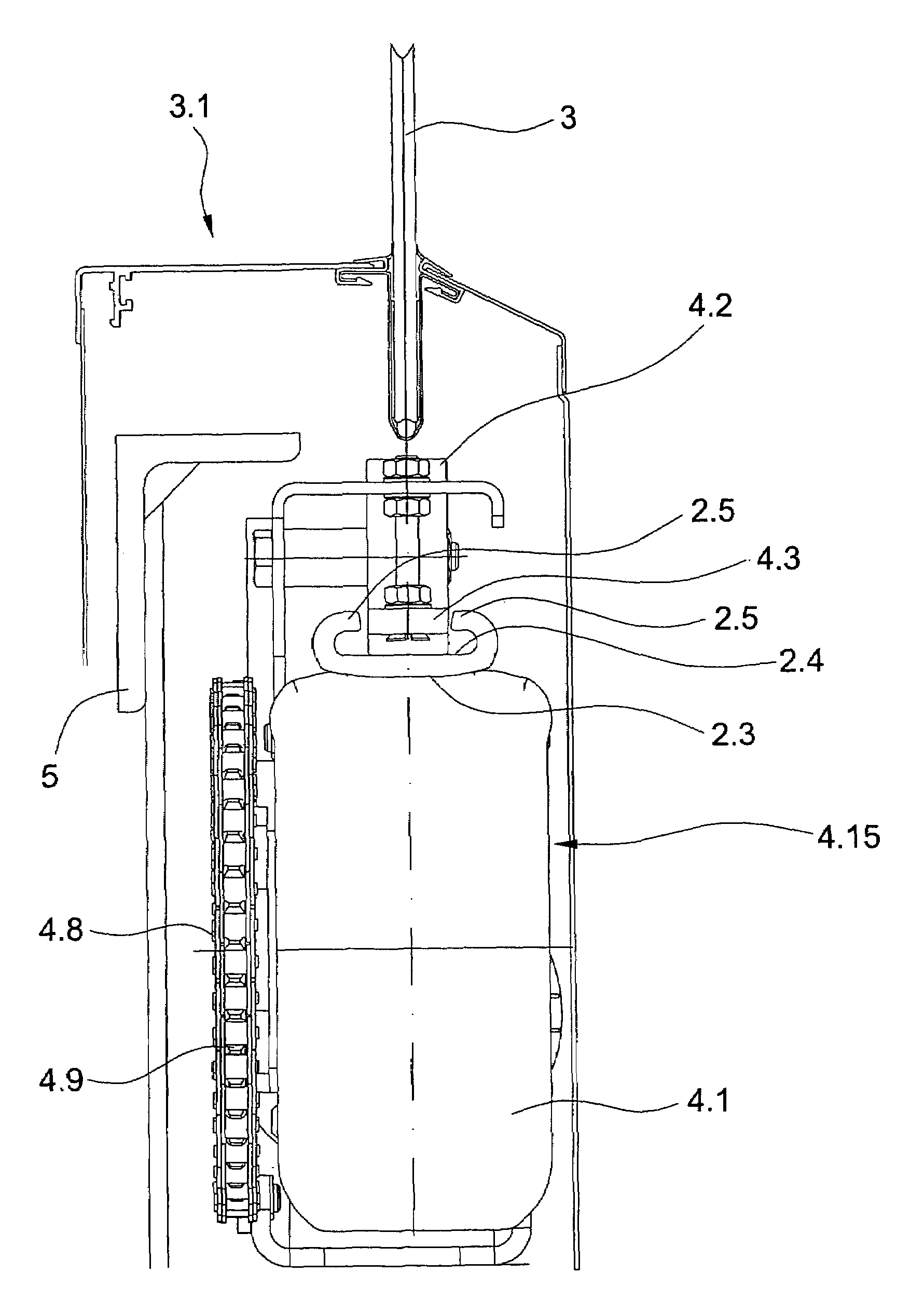
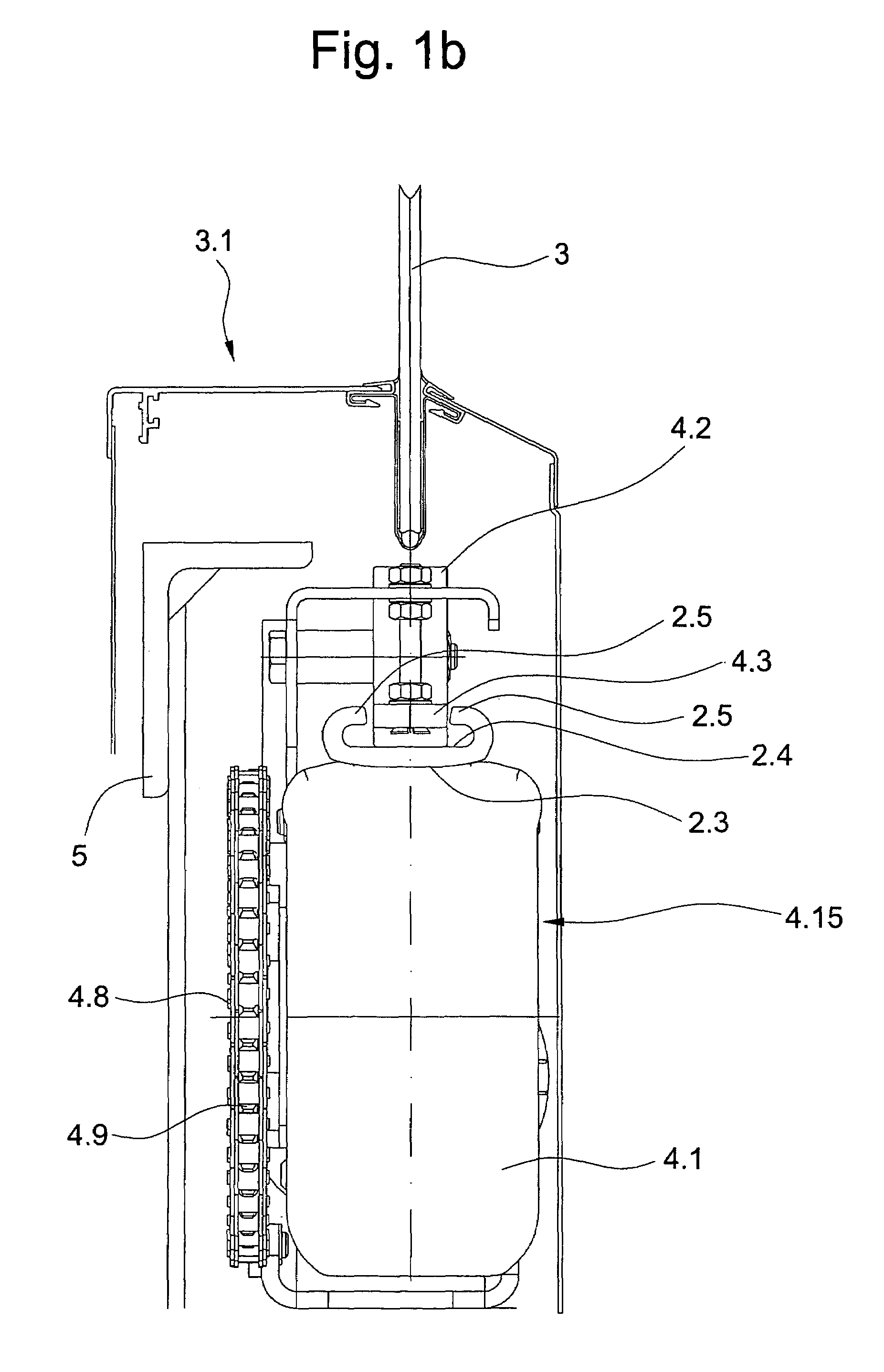
[0004]It is a purpose of the present invention to provide a handrail-drive that overcomes the shortcomings of the prior art, and provides a drive that can operate with reduced force applied to the handrail and with a greater contact area and reduced friction. Such and other objectives are accomplished by a handrail-drive that engages an outside of the handrail. The drive may include a drive-wheel for frictional engagement with the handrail outside, as well as a press-on roller engaging an inside of the handrail to press the handrail against the drive-wheel.
[0005]The advantages achieved by the handrail-drive according to the invention include that the pressure with which the drive-wheel tire and follower-wheel press onto the handrail can be reduced. Because of a greater contact surface of the drive-wheel, more power can be transmitted to the handrail. Due to the springing properties of the drive-wheel tire and the greater contact surface that results therefrom, the handrail is deformed only slightly or insignificantly. A further advantage is that the service life of the drive-wheels, the follower-wheels, and the handrail is increased. Also, dust and / or particles of dirt are prevented from being pressed into the casing of the handrail and / or into the outside of the handrail. The formation of grooves, cracks, or pressure points in the handrail can be avoided with the handrail-drive according to the invention. Roller damage due to flexing work is eliminated because the flexing work is largely absorbed by the filling material, for example, compressed air or inert gases, of the drive-wheel tire.

Problems solved by technology

A disadvantage of the known device is that the follower-wheel must exert a high pressing force so that no slip can occur between the handrail and the drive-wheel.
The high flexing work shortens the service life of the drive-wheels and of the follower-wheels.

Method used


Image

  • Handrail-drive for an escalator or a moving walk
  • Handrail-drive for an escalator or a moving walk
  • Handrail-drive for an escalator or a moving walk

Examples


Embodiment Construction

[0014]The handrail-drive according to the invention can also be used on moving walks with pallets. In the rest of the description as follows, only the term “escalator” will be used, but the statements made also apply analogously for a moving walk. As used herein, an “escalator” is construed to also encompass a moving walk, while the terms “step-band” and “steps” are to encompass a pallet band and pallets, respectively, in a moving walk construction.

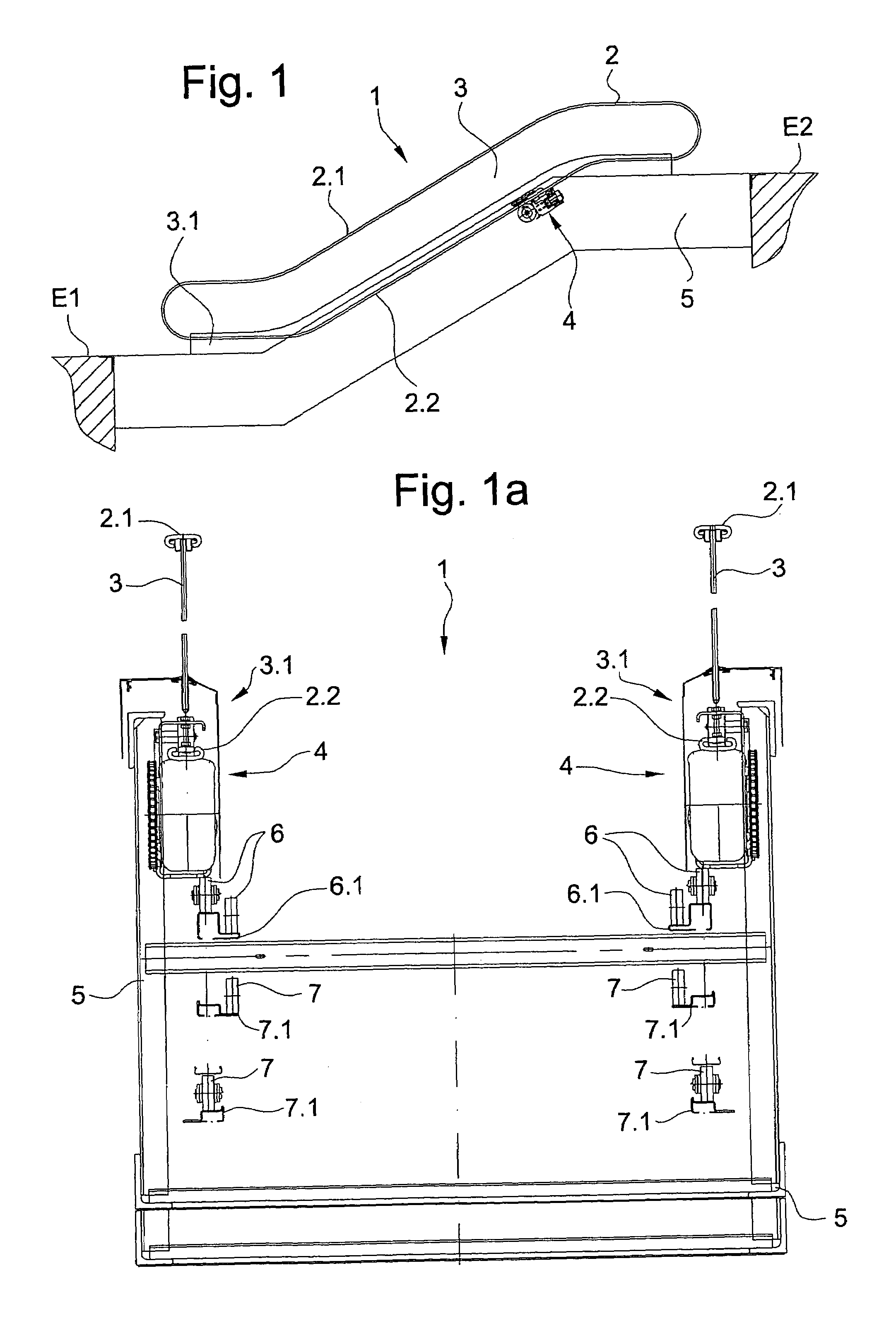
[0015]FIG. 1 shows a side view of an escalator 1 which connects a first landing E1 with a second landing E2. The escalator 1 has a step-band comprising steps. A handrail 2 with a riding-side 2.1 and a return-side 2.2 is arranged on a balustrade 3, which is held at the lower end by means of a balustrade base 3.1. The balustrade base 3.1 is supported by a truss 5 of the escalator 1. A handrail-drive 4 arranged on the truss 5 drives the handrail 2. Arranged at both the upper and the lower end-area of the escalator 1 is a combplate, which ens...


PUM


Abstract

A handrail-drive for an escalator or moving walk drives the handrail through frictional contact with an outside surface of the handrail. Press-on rollers engaging the inside of the handrail may be employed to press the handrail against a drive-wheel of the drive. The force of the rollers may be adjustable. The drive-wheel may include a gas-filled tire on a rim and can be driven by a motor, a step-chain wheel, or a step-chain drive.

Description

[0001]The present invention relates to an escalator or a moving walk comprising a truss, a step-band with steps or a pallet-band with pallets for the transportation of persons and / or objects, and on each side a balustrade which is held by a balustrade base and has a handrail, the handrail being driven by a handrail-drive.BACKGROUND OF THE INVENTION[0002]From patent specification EP 640 553 A2 a linear handrail-drive for an escalator has become known. Two drive-wheels with frictional engagement on the inside of the handrail move the handrail, there being provided on the outside of the handrail for each drive-wheel a follower-wheel which presses the handrail against the drive-wheel.[0003]A disadvantage of the known device is that the follower-wheel must exert a high pressing force so that no slip can occur between the handrail and the drive-wheel. The high flexing work shortens the service life of the drive-wheels and of the follower-wheels.BRIEF DESCRIPTION OF THE INVENTION[0004]It i...

Claims


Application Information

Patent Timeline
Patent Type & Authority Patents(United States)
IPC IPC(8): B66B23/04
CPCB66B23/04
Inventor ILLEDITS, THOMASHOLZL, HUBERT
Owner INVENTIO AG
Learn More