Locking nosepiece and template

a nosepiece and template technology, applied in the field of nosepieces, can solve the problems of high accuracy, time-consuming and labor-intensive, and the ability of the operator to limit the accuracy of such a method, and achieve the effect of convenient operation, accurate positioning and positioning

Inactive Publication Date: 2005-12-06
THE BOEING CO
View PDF9 Cites 16 Cited by
  • Summary
  • Abstract
  • Description
  • Claims
  • Application Information

AI Technical Summary

Benefits of technology

[0008]The present invention provides an improved apparatus for forming features in a workpiece. The apparatus can support a tool, such as a drill, proximate to a workpiece so that the tool can drill a hole or otherwise form a feature in the workpiece. Advantageously, the apparatus includes a nosepiece that can be easily secured to a boss in a predetermined location relative to the workpiece. The boss can be defined by a template, which can correspond to the geometrical configuration of the workpiece. Further, the apparatus allows the tool to be accurately positioned and operated without undue effort on the part of the operator.

Problems solved by technology

Manual layout and forming of the holes by an operator is a relatively inexpensive method of manufacture but is time-consuming and labor-intensive, and the accuracy of such a method is limited by the ability of the operator.
Alternatively, automation of the process, for example, with a computer numerical controlled (CNC) machine or a robot, can result in high accuracy but is also typically expensive.
Further, due to the geometrical configuration of some workpieces, it may be difficult or impossible to use a CNC machine or robot to access some portions of the workpiece to form the features.
However, because the operator may be unable to precisely maintain the drilling device in the desired relationship with the bushing and template, the operator typically uses a drill bit that is somewhat smaller than the desired size of the holes to form pilot holes while the template is in place.
In either case, using the template is time-consuming, and the placement and angle of the holes is affected by the skill of the operator.
Further, the operator may be fatigued quickly due to the torque and the normal force that he or she must apply to resist the rotation of the drill and advance the drill bit through the workpiece.
However, drill plates are typically expensive and require significant time for set up.
Additionally, the drill plates are expensive to manufacture and maintain, and each drill plate may not be useful for forming more than one particularly configured workpiece.

Method used


Image

  • Locking nosepiece and template
  • Locking nosepiece and template
  • Locking nosepiece and template

Examples


Embodiment Construction

[0017]The present invention now will be described more fully hereinafter with reference to the accompanying drawings, in which some, but not all embodiments of the invention are shown. Indeed, this invention may be embodied in many different forms and should not be construed as limited to the embodiments set forth herein; rather, these embodiments are provided so that this disclosure will satisfy applicable legal requirements. Like numbers refer to like elements throughout.

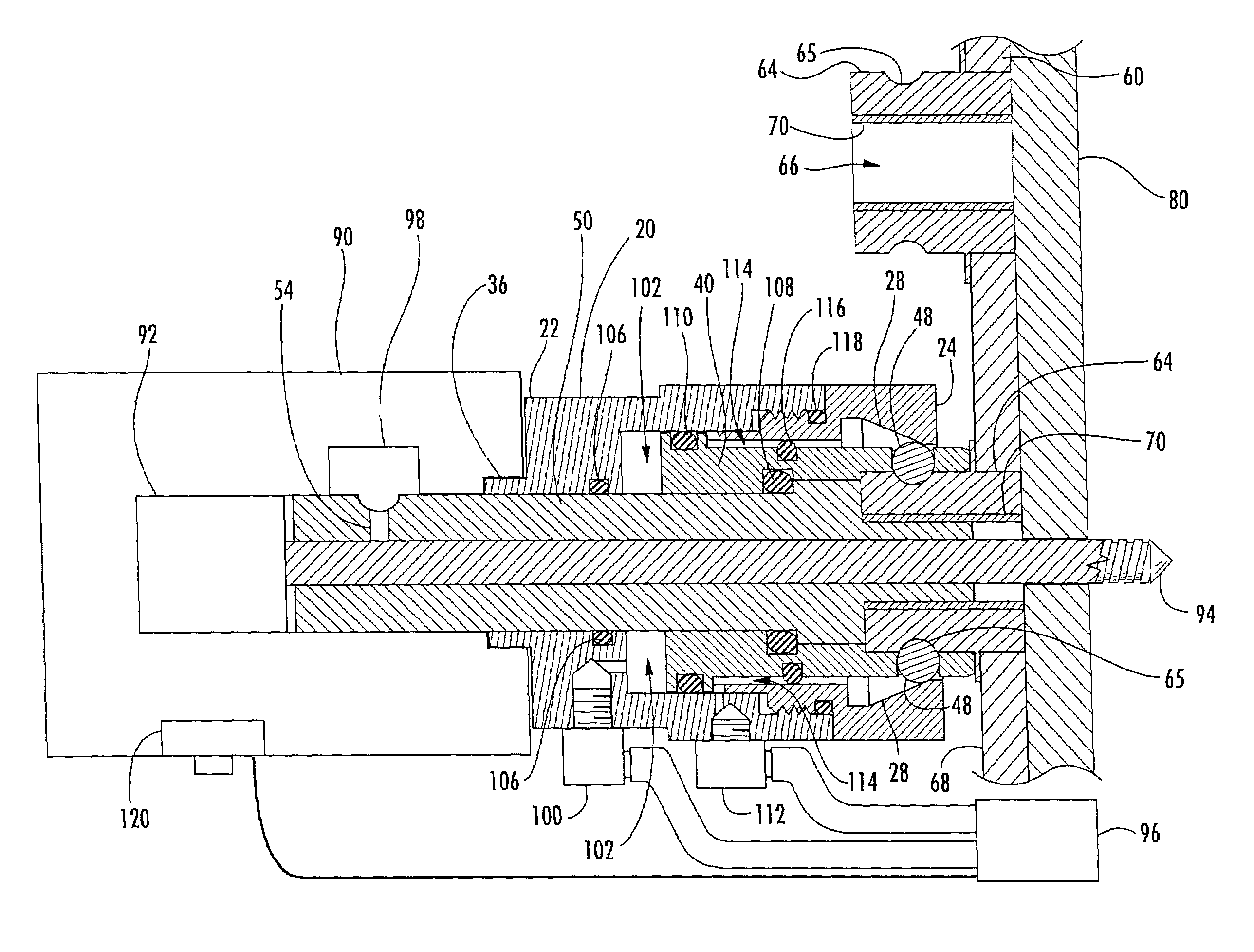
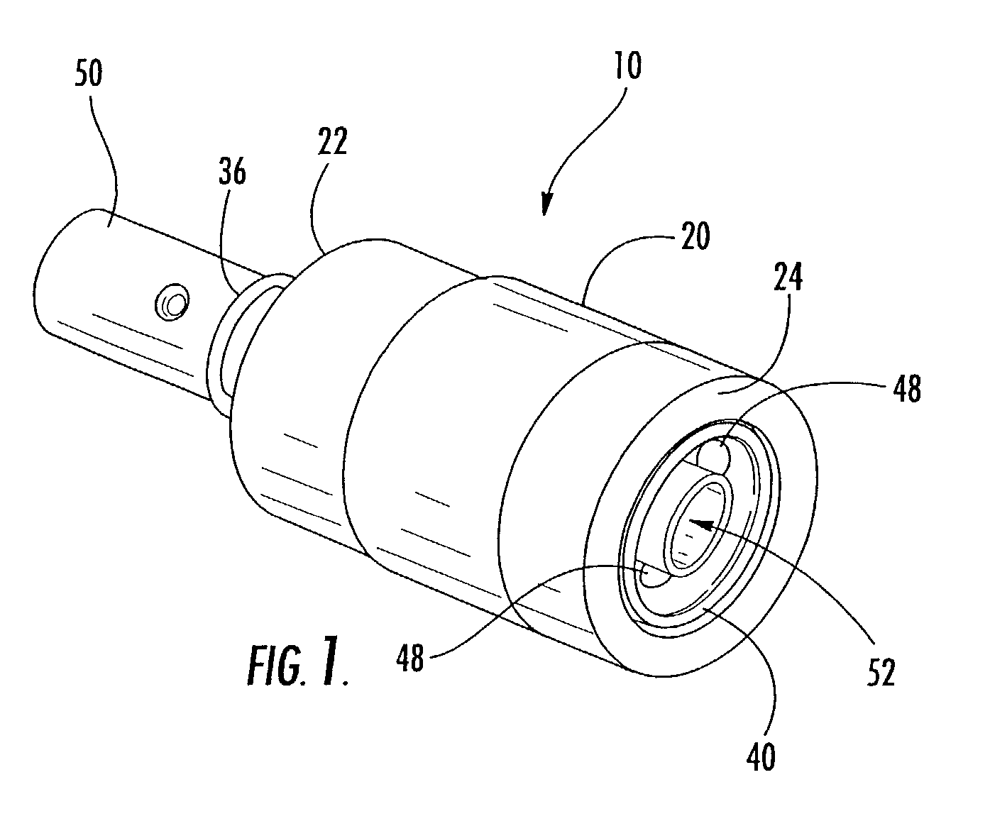
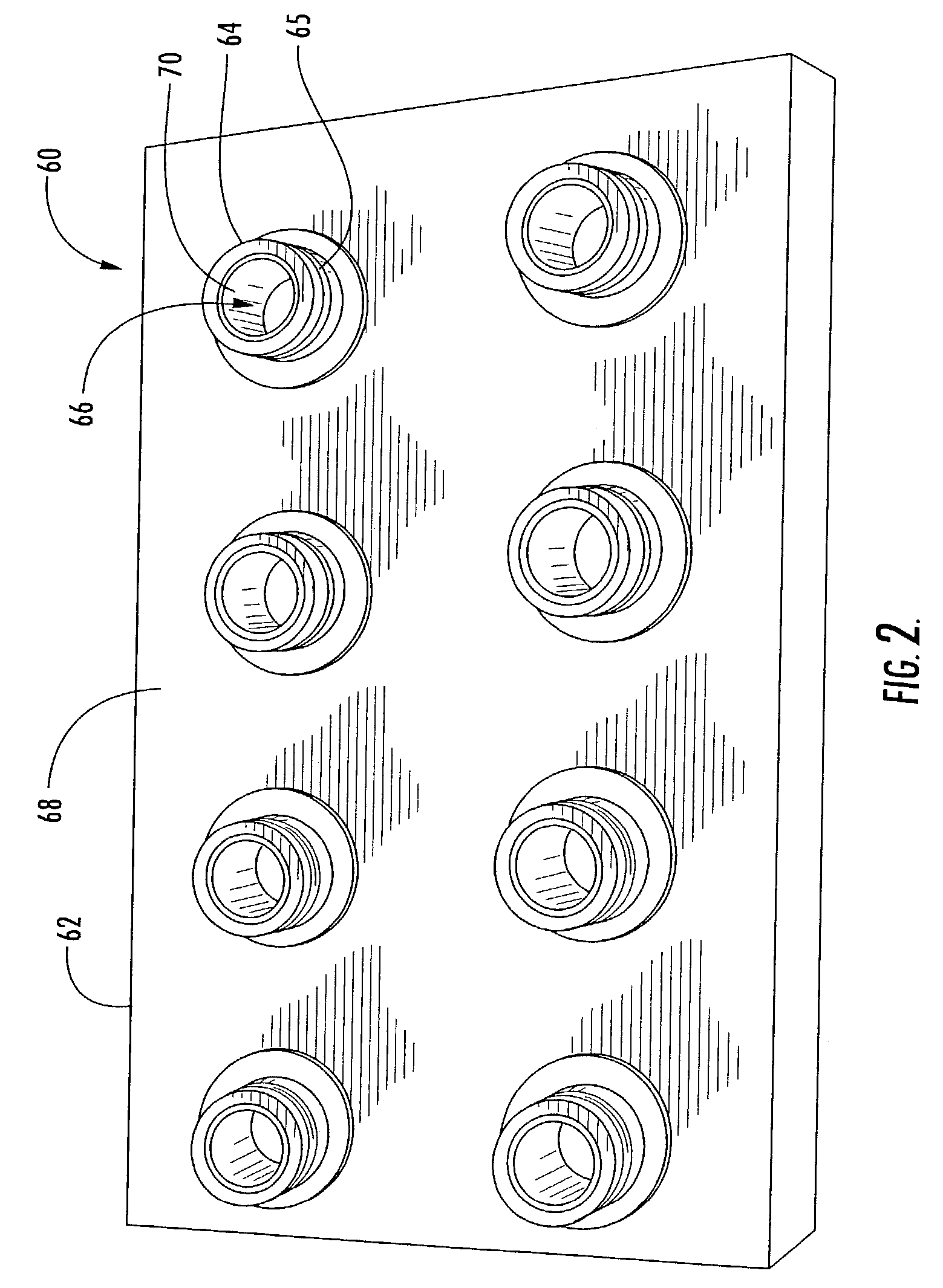
[0018]Referring now to the figures and, in particular, FIG. 1, there is shown a locking nosepiece 10 for engaging a boss 64 (FIG. 2) and guiding a tool member through the boss 64. The nosepiece 10 can be used in conjunction with a variety of tools and tool members for performing various functions on a workpiece. For example, the nosepiece 10 can be connected to a drill and sequentially used to guide a rotatable drill bit through a plurality of the bosses 64 provided on a template 60. Alternatively, the nosepiece 1...


PUM

PropertyMeasurementUnit
axial forceaaaaaaaaaa
structuresaaaaaaaaaa
thicknessaaaaaaaaaa

Abstract

An apparatus for forming features in a workpiece is provided. The apparatus includes a nosepiece that engages a boss of a template and guides a tool member therethrough. The nosepiece includes a housing and an adjustable member positioned at least partially in an interior space of the housing. The adjustable member defines radial apertures that hold locking members such as spherical bearings. The locking members are configured to contact a tapered portion of the inner surface of the housing so that as the adjustable member is adjusted from an unlocked position to a locked position, the locking members contact the tapered portion of the housing and are urged radially inward to retain the boss.

Description

BACKGROUND OF THE INVENTION[0001]1) Field of the Invention[0002]The present invention relates to an apparatus for engaging a tool with a workpiece and, more particularly, a nosepiece that can be secured to a template or another device to support a tool, such as a drill, proximate to a workpiece.[0003]2) Description of Related Art[0004]During the manufacture of a workpiece, it is often desirable to form features such as holes at a number of predetermined locations. Manual layout and forming of the holes by an operator is a relatively inexpensive method of manufacture but is time-consuming and labor-intensive, and the accuracy of such a method is limited by the ability of the operator. Alternatively, automation of the process, for example, with a computer numerical controlled (CNC) machine or a robot, can result in high accuracy but is also typically expensive. Further, due to the geometrical configuration of some workpieces, it may be difficult or impossible to use a CNC machine or r...

Claims


Application Information

Patent Timeline
Patent Type & Authority Patents(United States)
IPC IPC(8): B23B47/28B23Q1/00B23Q9/00
CPCB23B47/28B23B49/023B23Q9/0042B23Q1/0063Y10T408/56245Y10T408/08
Inventor BLANKENSHIP, THOMAS O.HARPER, KENNETH D.MARTINEK, BRIAN J.MORRISON, JAMES L.
Owner THE BOEING CO
Why Eureka
Try Eureka