Surface acoustic wave ladder filter device having resonators with different electrode pitches and electrostatic capacitances

a technology of ladder filter and surface acoustic wave, which is applied in piezoelectric/electrostrictive/magnetostrictive devices, piezoelectric/electrostriction/magnetostriction machines, electrical equipment, etc., can solve the problems of increasing insertion loss at the edges of the pass band, ineffective technique, and ineffective in preventing the increase in insertion loss and attenuation. , to achieve the effect of reducing the loss at the edg

Inactive Publication Date: 2005-12-06
TAIYO YUDEN KK
View PDF19 Cites 16 Cited by
  • Summary
  • Abstract
  • Description
  • Claims
  • Application Information

AI Technical Summary

Benefits of technology

[0009]To achieve the above object, the present invention provides a surface acoustic wave device that has surface acoustic wave resonators connected in a multi-stage ladder arrangement, including: two or more different comb-like drive electrode pitches of parallel-arm resonators and two or more different comb-like drive electrode pitches of series-arm resonators; reflection electrodes placed at either side of a comb-like drive electrode having a pitch different from that of said comb-like drive electrode; and two or more different electrostatic capacitances of parallel-arm resonators and two or more different electrostatic capacitances of series-arm resonators. With this structure, bulk wave radiation can be scattered, and spurious peaks inside and outside the pass band can also be scattered and reduced. Also, impedance mismatching can be reduced. Furthermore, loss at the edges of the pass band can be reduced, and the insertion loss characteristics and shape factor can be improved.

Problems solved by technology

The increases in insertion loss have hindered improvements in terms of insertion loss and attenuation in the vicinity of the pass band.
However, this technique is not effective enough to prevent spurious peaks that are caused by bulk wave radiation of the series-arm resonators and spurious peaks that appear outside the pass band.
However, this is not effective enough to prevent the increases in insertion loss at the edges of the pass band, either.

Method used


Image

  • Surface acoustic wave ladder filter device having resonators with different electrode pitches and electrostatic capacitances
  • Surface acoustic wave ladder filter device having resonators with different electrode pitches and electrostatic capacitances
  • Surface acoustic wave ladder filter device having resonators with different electrode pitches and electrostatic capacitances

Examples


first embodiment

(First Embodiment)

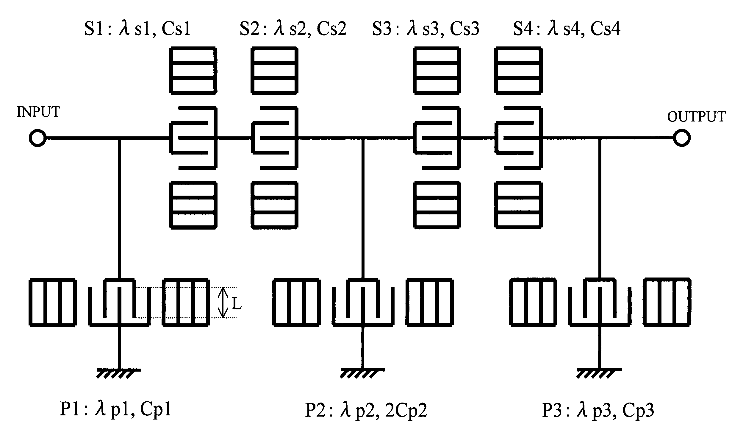
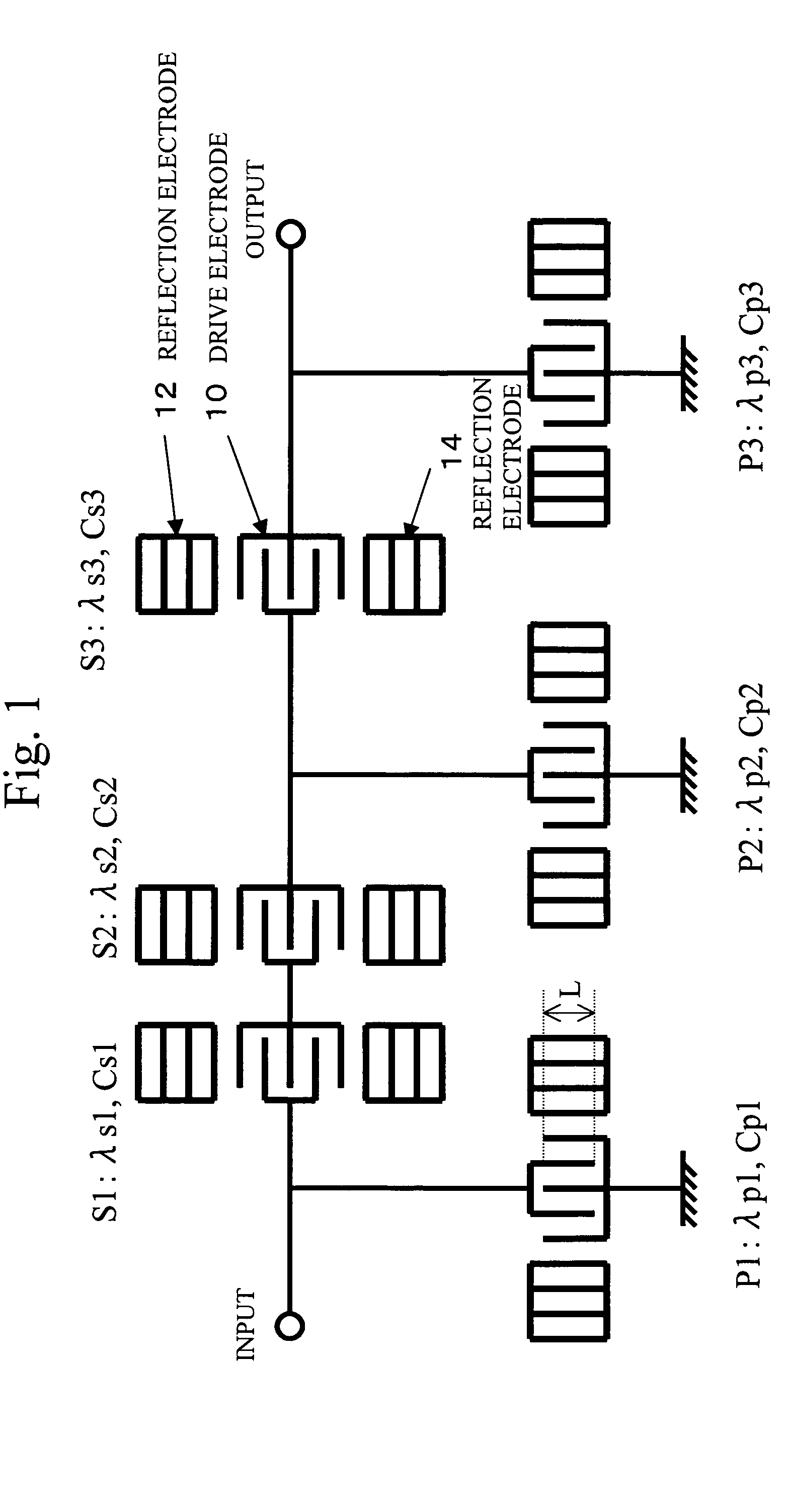
[0046]A first embodiment of the present invention is as follows. As shown in FIG. 7, a ladder filter having resonators P1-S1-S2-P2-S3-S4-P3 connected in this order is formed with Al alloy on a piezoelectric substrate of 42° Y—X LiTaO3, so as to cope with a PCS reception filter (with a pass band of 1930 through 1990 MHz and an attenuation (transmission) band of 1850 through 1910 MHz). The parallel-arm resonator P1 has an IDT pitch λP1 of 2.024 μm, a reflection electrode pitch λrefP1 of 2.044 μm, an aperture length LP1 of 54.6 μm, and 20 pairs (NP1) of drive electrode fingers. The parallel-arm resonator P2 has an IDT pitch λP2 of 2.043 μm, a reflection electrode pitch λrefP2 of 2.063 μm, an aperture length LP2 of 83.8 μm, and 72 pairs (NP2) of drive electrode fingers. The parallel-arm resonator P3 has an IDT pitch λP3 of 2.018 μm, a reflection electrode pitch λrefP3 of 2.038 μm, an aperture length LP3 of 54.5 μm, and 20 pairs (NP3) of drive electrode fingers. The ser...

second embodiment

(Second Embodiment)

[0049]This embodiment is a filter with the same structure as the structure shown in FIG. 1. In this filter, the parallel-arm resonator P2 with the greatest electrostatic capacitance among the parallel-arm resonators P1 through P3 has the longest IDT pitch. The parallel-arm resonator P1 has an IDT pitch λP1 of 2.032 μm, a reflection electrode pitch λrefP1 of 2.052 μm, an aperture length LP1 of 54.9 μm, and 42 pairs (NP1) of drive electrode fingers. The parallel-arm resonator P2 has an IDT pitch λP2 of 2.040 μm, a reflection electrode pitch λrefP2 of 2.060 μm, an aperture length LP2 of 84.3 μm, and 84 pairs (NP2) of drive electrode fingers. The parallel-arm resonator P3 has an IDT pitch λP3 of 2.032 μm, a reflection electrode pitch λrefP3 of 2.052 μm, an aperture length LP3 of 54.9 μm, and 40 pairs (NP3) of drive electrode fingers. The series-arm resonators S1 and S2 each has an IDT pitch (λS1=λS2) of 1.952 μm, a reflection electrode pitch (λrefS1=λrefS2) of 1.947 μ...

third embodiment

(Third Embodiment)

[0051]This embodiment is a filter with the same structure as the structure shown in FIG. 1. In this filter, the parallel-arm resonator P3 with the shortest IDT pitch among the parallel-arm resonators P1 through P3 has the smallest electrostatic capacitance. The parallel-arm resonator P1 has an IDT pitch λP1 of 2.032 μm, a reflection electrode pitch λrefP1 of 2.052 μm, an aperture length LP1 of 54.9 μm, and 42 pairs (NP1) of drive electrode fingers. The parallel-arm resonator P2 has an IDT pitch λP2 of 2.032 μm, a reflection electrode pitch λrefP2 of 2.052 μm, an aperture length LP2 of 84.0 μm, and 84 pairs (NP2) of drive electrode fingers. The parallel-arm resonator P3 has an IDT pitch λP3 of 2.022 μm, a reflection electrode pitch λrefP3 of 2.042 μm, an aperture length LP3 of 54.6 μm, and 40 pairs (NP3) of drive electrode fingers. The series-arm resonators S1 and S2 each has an IDT pitch (λS1=λS2) of 1.952 μm, a reflection electrode pitch (λrefS1=λrefS2) of 1.947 μ...


PUM


Abstract

A surface acoustic wave device that has surface acoustic wave resonators connected in a multi-stage ladder arrangement, includes: two or more different pitches of comb-like drive electrodes of parallel-arm resonators (P1˜P3) and two or more different pitches of comb-like drive electrodes of series-arm resonators (S1˜S3); reflection electrodes (12, 14) placed at either side of a comb-like drive electrode having a pitch different from that of said comb-like drive electrode; and two or more different electrostatic capacitances of parallel-arm resonators and two or more different electrostatic capacitances of series-arm resonators.

Description

CROSS-REFERENCE TO RELATED APPLICATION[0001]This application is a continuation of Application No. PCT / JP03 / 01165, filed Feb. 5, 2003, the entire specification claims and drawings of which are incorporated herewith by reference.FIELD OF THE INVENTION[0002]The present invention relates to surface acoustic wave devices, and more particularly, to a surface acoustic wave device that has surface acoustic wave resonators connected in a multi-stage ladder arrangement.[0003]In recent years, wireless devices such as portable telephone devices have been rapidly becoming smaller and sophisticated. Filters that are used in the high frequency circuits of those wireless devices play important roles in this development. Especially, surface acoustic wave devices are used to embody such filters.BACKGROUND OF THE INVENTION[0004]FIG. 1 schematically illustrates a surface acoustic wave device that has surface acoustic wave resonators connected in a multi-stage ladder arrangement. The surface acoustic wa...

Claims


Application Information

Patent Timeline
Patent Type & Authority Patents(United States)
IPC IPC(8): H03H9/25H03H9/64
CPCH03H9/25H03H9/6483H03H9/64
Inventor NISHIZAWA, TOSHIOHATTANDA, TOMOKA
Owner TAIYO YUDEN KK
Why Eureka
Try Eureka