Display control apparatus and display control method

a control apparatus and display control technology, applied in the field of display control apparatus and display control method, can solve the problems of deteriorating picture quality, reducing light utilization efficiency, and reducing light amount, so as to achieve the effect of reducing the appearance of moving picture pseudo contours

Inactive Publication Date: 2005-12-06
SONY CORP
View PDF27 Cites 27 Cited by
  • Summary
  • Abstract
  • Description
  • Claims
  • Application Information

AI Technical Summary

Benefits of technology

[0017]In the display control apparatus and the display control method, a signal is produced for driving the display apparatus so that light of divisional light amounts obtained by dividing light amounts corresponding to bits which compose digital values may be emitted in such a manner as to be distributed within a time corresponding to one screen. In this instance, where both of a first light amount corresponding to a

Problems solved by technology

Accordingly, the timing at which a pixel is controlled to on or off is displaced among the different bit planes, and therefore, when a moving picture is displayed, a moving picture pseudo contour appears and deteriorates the picture quality.
According to the method, however, since the time within which a pixel is on within the entire time of one frame is reduced, this gives rise to redu

Method used


Image

  • Display control apparatus and display control method
  • Display control apparatus and display control method
  • Display control apparatus and display control method

Examples


first embodiment

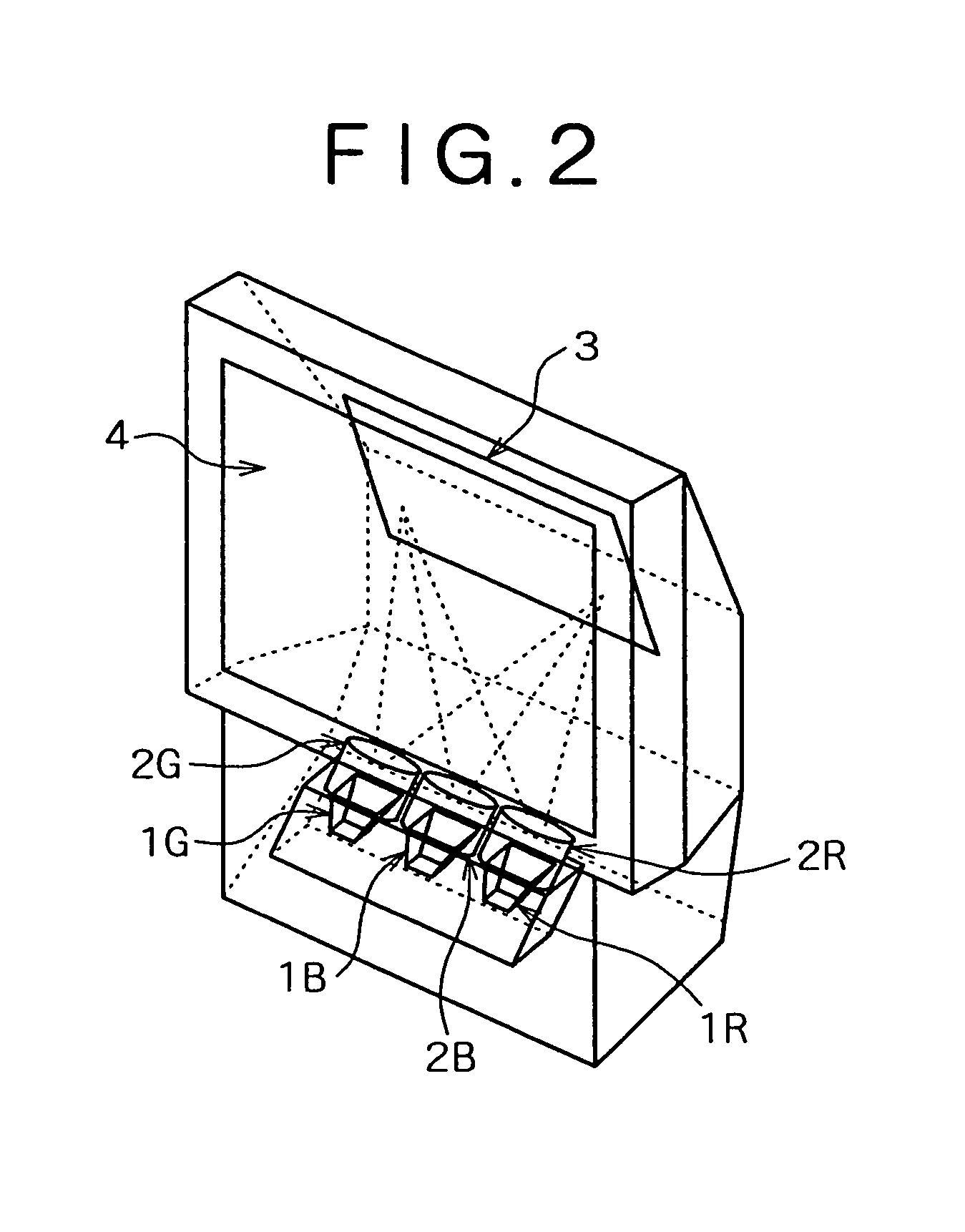
[0053]FIG. 2 shows an example of appearance configuration of a display apparatus according to a first embodiment of the present invention.

[0054]The present display apparatus is a projector which uses a CRT (Cathode Ray Tube), and an R CRT 1R, a G CRT 1G and a B CRT 1B emit light of components (color components) of R (Red), G (Green) and B (Blue) of an image, respectively. The light of the R component, the light of the G component and the light of the B component pass through an R projection lens 2R, a G projection lens 2G and a B projection lens 2B, respectively, and are irradiated upon a reflecting mirror 3. The light of the R component, the light of the G component and the light of the B component irradiated upon the reflecting mirror 3 are reflected by the reflecting mirror 3 and irradiated upon a transmission screen 4. Consequently, an image formed from the R, G and B components is displayed on the transmission screen 4.

second embodiment

[0055]FIG. 3 shows an example of appearance configuration of a display apparatus according to a second embodiment of the present invention. Referring to FIG. 3, the display apparatus is configured in a similar manner to that in FIG. 2 except that a liquid crystal projector 11 is provided in place of the R CRT 1R, G CRT 1G and B CRT 1B as well as the R projection lens 2R, G projection lens 2G and B projection lens 2B.

[0056]The liquid crystal projector 11 is formed from a liquid crystal panel, a lens and so forth not shown, and enlarges an image displayed on the liquid crystal panel by means of the lens and irradiates corresponding light upon the reflecting mirror 3. An image of the light reflected from the reflecting mirror 3 is displayed on the transmission screen 4.

third embodiment

[0057]FIG. 4 shows an example of appearance configuration of a display apparatus according to a third embodiment of the present invention.

[0058]The present display apparatus is an HMD (Head Mounted Display) apparatus, and a user uses the display apparatus with a head mounting section 23 mounted on the head thereof such that a lens 22 may be opposed to the pupils of the user itself.

[0059]In this instance, light as an image displayed on an image display panel 21 formed from a CRT, a liquid crystal panel or the like of a small size is introduced into the pupils of the user through the lens 22. Thereupon, a virtual image of a predetermined size is observed at a position spaced by a predetermined distance by the pupils of the user.

[0060]The present invention can be applied also to a PDP or a display apparatus which uses an LED (Light Emitting Diode) as a pixel.

[0061]FIG. 5 shows an example of electric configuration of a display apparatus to which the present invention is applied.

[0062]Di...


PUM


Abstract

The invention provides a display control apparatus and a display control method wherein, where digital gradation display is performed, occurrences of a moving picture pseudo contour can be reduced simply. A signal production circuit produces a signal for driving a display section so that light of divisional light amounts obtained by dividing light amounts corresponding to bits which compose digital values which are pixel values may be emitted in a such manner as to be distributed within a time corresponding to one screen. In this instance, where both of a first light amount corresponding to a predetermined bit and a second light amount corresponding to a bit in a lower order by one bit to the bit are divided, the first and second light amounts are divided so that the division number of the first light amount may be smaller than twice the division number of the second light amount.

Description

BACKGROUND OF THE INVENTION[0001]This invention relates to a display control apparatus and a display control method, and more particularly to a display control apparatus and a display control method by which, when digital gradation display is performed, appearances of a moving picture pseudo contour can be reduced simply.[0002]Conventional image display apparatus commonly adopt an analog gradation display system of displaying each pixel in an analog gradation. In recent years, however, also an image display apparatus which adopts a digital gradation display system based on PWM (Pulse Width Modulation) has been realized.[0003]Image display apparatus which adopt the digital gradation display system include, for example, a PDP (Plasma Display Panel), a display unit which uses a light valve which is a display element for switching (transmitting / intercepting) light from a light source on / off, and so forth. As the light valve, for example, a liquid crystal panel which uses FLC (Ferroelect...

Claims


Application Information

Patent Timeline
IPC IPC(8): G09G3/20H04N5/20G09G3/28G09G3/296G09G3/34H04N5/66H04N5/74H04N9/31H04N9/69
CPCG09G3/2033G09G3/2081G09G3/3406H04N9/3123H04N9/3197H04N9/69G09G3/2022G09G3/2025G09G3/28G09G3/34G09G2320/0266G09G2320/0276G09G2320/0633G09G2320/064H04N5/7408H04N5/7416H04N9/31
Inventor MATSUI, TAKESHINISHI, TOMOHIRO
Owner SONY CORP
Why Eureka
Try Eureka