
Space-variant subwavelength polarization grating and applications thereof

a polarization grating and space-variant technology, applied in the field of polarization gratings, can solve problems such as degrading the optical efficiency of polarizers

Inactive Publication Date: 2005-12-06
TECHNION RES & DEV FOUND LTD
View PDF4 Cites 43 Cited by
  • Summary
  • Abstract
  • Description
  • Claims
  • Application Information

AI Technical Summary

Benefits of technology

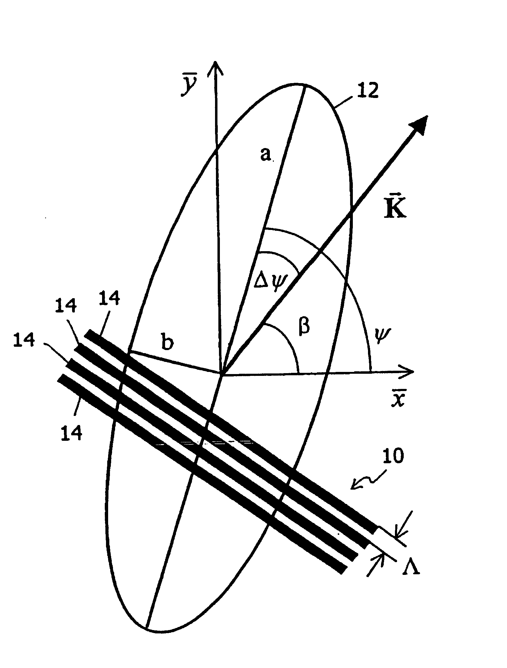
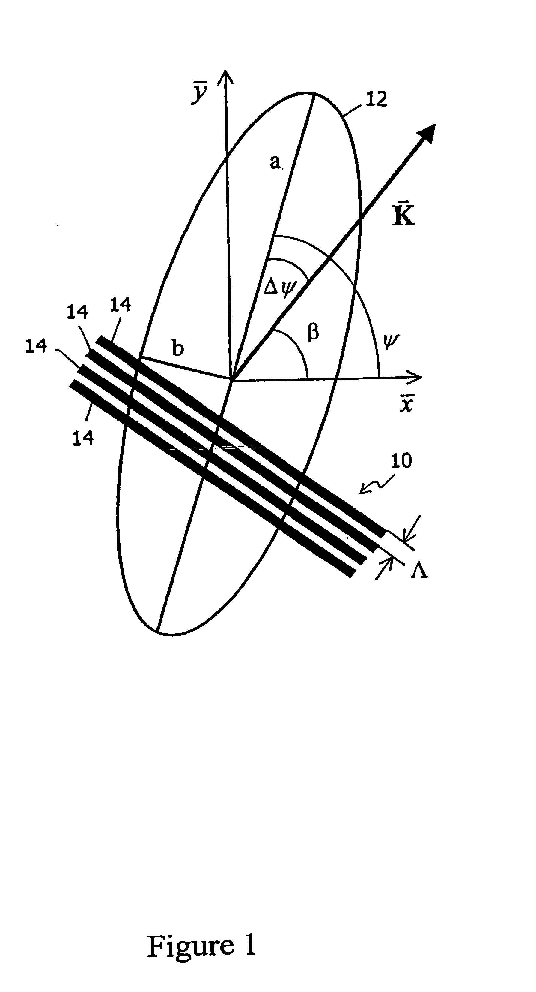
[0018]According to the present invention, the grating is a subwavelength grating, meaning that the local period of at least a portion of the grating is less than the maximum wavelength of the light that is manipulated by the grating. It is to be understood that the present invention may be used to manipulate either monochromatic light or polychromatic light. All references herein to a “maximum” wavelength are to the wavelength that is used to define the “subwavelength” nature of the grating. One consequence of the subwavelength nature of the grating is that the transmitted beam is substantially free of propagating orders higher than zero order.

Problems solved by technology

Discontinuities in the lateral variation of the transmission axis of a polarizer can produce diffractions which degrade the optical efficiency of the polarizer.

Method used


Image

  • Space-variant subwavelength polarization grating and applications thereof
  • Space-variant subwavelength polarization grating and applications thereof
  • Space-variant subwavelength polarization grating and applications thereof

Examples


Embodiment Construction

[0056]The present invention is of a polarization grating which can be used to impose, on incident electromagnetic radiation, a laterally varying intensity modulation or a laterally varying polarization state.

[0057]The principles and operation of a polarization grating according to the present invention may be better understood with reference to the drawings and the accompanying description.

[0058]Gori defined a “polarization grating” as “a transparency in which the polarization of the incident wave is changed periodically along a line”. The present invention defines a “polarization grating” somewhat more generally, as an optical device that imposes a (not necessarily periodic) laterally varying intensity modulation, or alternatively a (not necessarily periodic) laterally varying polarization state, on an incident beam of electromagnetic radiation that is laterally uniform in intensity and polarization state. The lateral variation may be in one or both orthogonal directions transverse...


PUM

PropertyMeasurementUnit
anglesaaaaaaaaaa
anglesaaaaaaaaaa
thickaaaaaaaaaa

Abstract

An optical device includes a plurality of metallic stripes, arranged in a substantially planar, subwavelength grating having a laterally varying, continuous grating vector, deposited on a substrate such as GaAs or ZnSe. When used as a polarizer, the device passes a laterally uniform polarized beam of electromagnetic radiation incident thereon with a predetermined, laterally varying transmissivity. When used to effect polarization state transformation, the device transforms a beam of electromagnetic radiation incident thereon into a transmitted beam having a predetermined, laterally varying polarization state. The device can be used to provide radially polarized electromagnetic radiation for accelerating subatomic particles or for cutting a workpiece. The device also can be used, in conjunction with a mechanism for measuring the lateral variation of the intensity of the transmitted beam, for measuring the polarization state of the incident beam.

Description

[0001]This application claims benefit of Ser. No. 60 / 258,040 filed Dec. 27, 2000, And claims benefit of Ser. No. 60 / 304,096 filed Jul. 11, 2001, And claims benefit of Ser. No. 60 / 306,455 filed Jul. 20, 2001.FIELD AND BACKGROUND OF THE INVENTION[0002]The present invention relates to the production and manipulation of optically polarized light and, more particularly, to a polarization grating whose grating vector varies continuously laterally and applications of this grating.[0003]Laterally varying polarizers have found application in a variety of fields, including optical communication, optical computers, material processing, tight focusing, polarimetry, particle trapping and particle acceleration. For the most part, the transmission axes of these polarizers vary laterally in a discontinuous manner. For example, Bahram Javidi and Takanori Nomura, “Polarization encoding for optical security systems”, Optical Engineering vol. 39 no. 9 pp. 2439-2443 (2000), perform polarization encoding...

Claims


Application Information

Patent Timeline
Patent Type & Authority Patents(United States)
IPC IPC(8): B23K26/06G02B5/18G02B5/30G21K1/16
CPCB23K26/0639B23K26/0643B23K26/0648B23K26/0665G02B5/1809G02B5/1866G02B5/3058G21K1/16B23K26/064
Inventor HASMAN, EREZBOMZON, ZEEVKLEINER, VLADIMIR
Owner TECHNION RES & DEV FOUND LTD
Learn More