
Apparatus and method for memory saving wavelet based video coding

Inactive Publication Date: 2005-12-06
XVD TECH HLDG LTD IRELAND
View PDF4 Cites 22 Cited by
  • Summary
  • Abstract
  • Description
  • Claims
  • Application Information

AI Technical Summary

Benefits of technology

[0024]These embodiments have the advantage of providing a lower data rate without degrading the wavelet coefficient representation accuracy and at the same time they allow hardware real-time implementation.

Problems solved by technology

The number of bits needed to store a typical image is substantially large, therefore limiting the use of images in data processing and communication systems.
For example, normal consumer-quality analog telephone lines are limited to a digital communication rate of 33600 bits per second.
As a result, quantization errors tend to produce aliasing errors which are subjectively unsatisfactory.
This procedure reduces the computational work load, but leads to other undesirable artifacts in the reconstructed image, such as “blocking”.
However, wavelet based image compression coders are used less often than DCT-based coders despite their typically improved performance.
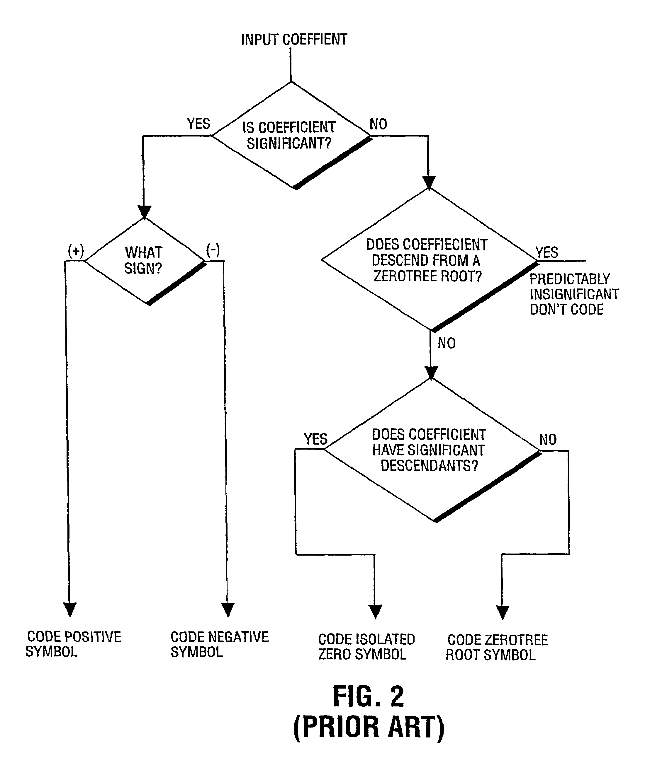
However, constructing a zero-tree is a rather complicated procedure which does not permit “on-the-fly” wavelet filtering followed by coding due to the necessity of the preliminary wavelet coefficient analysis.
Moreover the analysis time drastically increases as an image size grows.
Another problem appears when it is necessary to reduce the memory requirements for wavelet filtering.
In this case we can not use any global statistics since we have no access to the whole image or even a complete subband.
This method has the following drawbacks: it is efficient only for so-called sparse wavelet coefficient arrays (arrays with a small number of non-zero elements) and it requires a rather large memory for keeping wavelet coefficient arrays and their subblocks.
An effective video signal compression with an acceptable quality of synthesized video signal and a practical real time implementation with low memory requirements still remains a key problem.

Method used


Image

  • Apparatus and method for memory saving wavelet based video coding
  • Apparatus and method for memory saving wavelet based video coding
  • Apparatus and method for memory saving wavelet based video coding

Examples


Embodiment Construction

[0042]In the following description, numerous specific details are set forth to provide a thorough understanding of the invention. However, it is understood that the invention may be practiced without these specific details. In other instances, well-known structures and techniques have not been shown in detail in order not to obscure the invention.

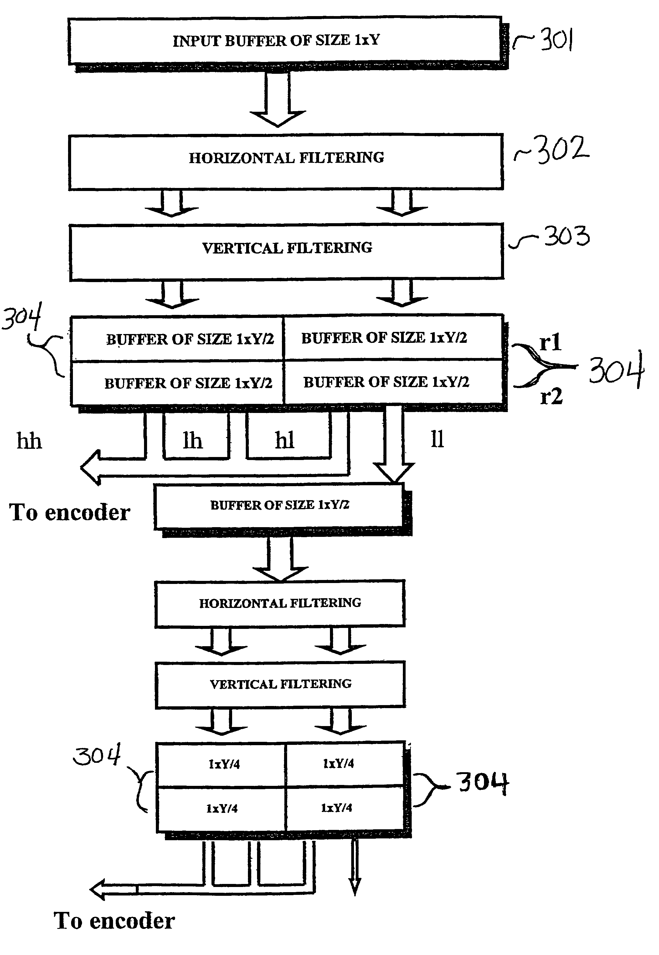
[0043]FIG. 3 is a block diagram illustrating the smaller buffer size used to save memory according to one embodiment of the invention. A row of an image is buffered in an input buffer 301. The row of the image stored in the input buffer is horizontally filtered 302 and then vertically filtered 303. Each buffer 304 is only half the size of the image data received from vertical filtering and independent of the filter length. The size of the buffers decreases by half for every filtering performed.

[0044]FIG. 4 is a block diagram of a video encoder 400, for still images and / or motion video according to one embodiment of the invention. The image ...


PUM


Abstract

A method and apparatus for compressing video signals. The video compression may include row by row horizontal subband filtering of video data representing part of an image, and row by row concurrent vertical high and vertical low pass subband filtering of the results of the horizontal subband filtering. Less than the vertical filter length of rows of results of the horizontal subband filtering may be buffered at a time. The vertical high and vertical low pass subband filtering may include calculating a first result row by adding a first row of a recursion buffer to the results of multiplying a row of results from the horizontal subband filtering and a first vertical filter coefficient, calculating a second result row by adding the first row of the recursion buffer to the result of multiplying the row of results of the horizontal subband filtering and a second vertical filter coefficient, overwriting the first row of the recursion buffer with the second result row, and transmitting the first result row to be encoded.

Description

NOTICE OF RELATED APPLICATION[0001]This application claims the benefit of U.S. Provisional patent application No. 60 / 171,890, entitled “Apparatus And Method For Memory Saving Wavelet Based Image / Video Coding”, filed Dec. 23, 1999.BACKGROUND OF THE INVENTION[0002]1. Field of the Invention[0003]The present invention relates to an apparatus and method of compressing a video signal. More particularly, an apparatus and method of compressing a video signal with wavelet transforms and encoding.[0004]2. Background of the Invention[0005]Image compression systems are useful to represent video information as accurately as possible with a minimum number of bits and thus minimize the amount of data which must be stored or transmitted. The number of bits needed to store a typical image is substantially large, therefore limiting the use of images in data processing and communication systems. For example, normal consumer-quality analog telephone lines are limited to a digital communication rate of ...

Claims


Application Information

Patent Timeline
IPC IPC(8): H04N7/12H04N7/26
CPCH04N19/63H04N19/61H04N19/13H04N19/42
Inventor KOLESNIK, VICTOR D.BOCHAROVA, IRINA E.KUDRYASHOV, BORIS D.MARSAVIN, ANDREYSIMILEYSKY, VICTORTAUBIN, FELIX A.
Owner XVD TECH HLDG LTD IRELAND
Learn More