Dynamic acoustic rendering

a dynamic acoustic rendering and virtual environment technology, applied in the field of acoustic modeling, can solve the problems of not providing real-time no system has been designed for dynamic acoustic rendering of virtual environment including multiple sources and moving objects in real time, and achieve the effect of efficient reus

Inactive Publication Date: 2005-12-06
CREATIVE TECH CORP +1
View PDF5 Cites 25 Cited by
  • Summary
  • Abstract
  • Description
  • Claims
  • Application Information

AI Technical Summary

Benefits of technology

[0008]A system for providing efficient real time dynamic acoustic rendering is disclosed. Wavetracing™ is used to simulate acoustic scenes in real time on an ordinary personal computer, workstation or game console. Acoustic surfaces are derived from a set of polygons provided by an application for graphics processing. Direct path 3D audio is augmented with acoustic reflections, dynamic reverberations, and occlusions generated by the acoustic surfaces. A three dimensional environment of listeners, sound sources and acoustic surfaces is derived from graphics data used by a graphics engine that is modified and reused to acoustically render a virtual scene. An acoustic environment that parallels a graphics scene being rendered is rendered from the perspective of the listener in the graphics scene. A subset of selected polygons from the graphics scene are rendered as acoustic surfaces and reflections or occlusions of the acoustic surfaces are modeled for sounds generated by sound sources. By judiciously selecting the subset of polygons to be rendered acoustically and optimizing the processing of the interaction of those surfaces with the sound sources, graphics data is efficiently reused to render an acoustic environment.

Problems solved by technology

However, current systems do not provide for real time dynamic acoustic rendering of such a virtual environment because of the processing demands of such a system.
Acoustic reflections have been modeled for simple environments such as a six sided box, but no system has been designed for dynamic acoustic rendering of a virtual environment including multiple sources and moving objects in real time.

Method used


Image

  • Dynamic acoustic rendering
  • Dynamic acoustic rendering
  • Dynamic acoustic rendering

Examples


Embodiment Construction

[0033]A detailed description of a preferred embodiment of the invention is provided below. While the invention is described in conjunction with that preferred embodiment, it should be understood that the invention is not limited to any one embodiment. On the contrary, the scope of the invention is limited only by the appended claims and the invention encompasses numerous alternatives, modifications and equivalents. For the purpose of example, numerous specific details are set forth in the following description in order to provide a thorough understanding of the present invention. The present invention may be practiced according to the claims without some or all of these specific details. For the purpose of clarity, details relating to technical material that is known in the technical fields related to the invention has not been described in detail in order not to unnecessarily obscure the present invention in such detail.

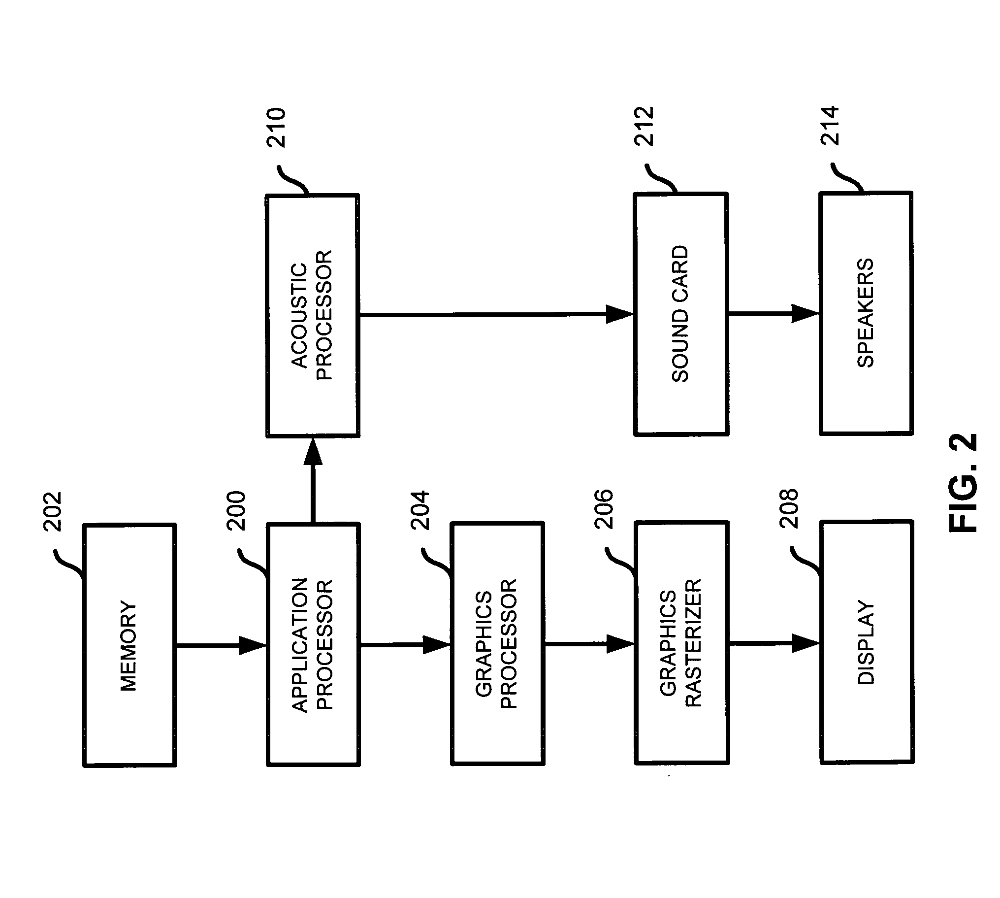
[0034]FIG. 2 is a block diagram of a system for rendering a vi...


PUM


Abstract

A method of acoustically rendering a virtual environment is described. The method includes receiving a subset of polygons derived for an acoustic display from a set of polygons generated for a graphical display. Acoustic reflections are determined from a sound source that bounce off of polygons in the subset of polygons to a listener position in the virtual environment. It is determined whether a polygon in the subset of polygons causes an occlusion of the sound source at the listener position, and a play list of sounds is generated based on the reflections and occlusions.

Description

FIELD OF THE INVENTION[0001]The present invention relates generally to acoustic modeling. More specifically, a system and method for rendering an acoustic environment including a listener, sound sources, occlusions, and reflections is disclosed.BACKGROUND OF THE INVENTION[0002]Direct path 3D audio is used to render sound sources in 3 dimensions to a listener. In addition to simulating the sources themselves, a more realistic experience may be provided to the user by also simulating the interaction of the sources with the objects in a virtual environment. Such objects may occlude certain sound sources from the listener and also may reflect sound sources. For example, sounds originating in a virtual room would sound differently to a listener depending on the size of the room and sounds originating in an adjacent room would sound differently depending on whether such sounds were occluded by a wall or were transmitted via a path through an open door. In an open environment, reflected so...

Claims


Application Information

Patent Timeline
Patent Type & Authority Patents(United States)
IPC IPC(8): H04R5/00H04S7/00
CPCH04S3/00H04S7/30
Inventor GERRARD, ALANDO, NAM
Owner CREATIVE TECH CORP
Why Eureka
Try Eureka