Millimeter wave band transmitter, millimeter wave band receiver and millimeter wave band communication apparatus carrying out radio communication in millimeter wave band region

a communication apparatus and millimeter wave band technology, applied in multiplex communication, frequency-division multiplex, resonant circuits using central processing units, etc., can solve the problems of spurious component reduction, radio transmission distance shortened, and significant power efficiency of the signal component that is to be originally transmitted, so as to achieve high transmission efficiency

Inactive Publication Date: 2005-12-06
SHARP KK
View PDF13 Cites 39 Cited by
  • Summary
  • Abstract
  • Description
  • Claims
  • Application Information

AI Technical Summary

Benefits of technology

[0015]In view of the foregoing, an object of the present invention is to provide a millimeter wave band transmitter, a millimeter wave band receiver and a millimeter wave band communication apparatus of high transmission efficiency.

Problems solved by technology

As a result, the power efficiency with respect to the signal component that is to be originally transmitted is degraded significantly.
There is a problem that the radio transmission distance is shortened.
However, it is difficult to form a carrier wave of the millimeter wave band reduced in spurious component.
Therefore, there was a problem that, if there is an overlap of the frequency components among the plurality of signals of the UHF band, such a signal cannot be multiplexed.

Method used


Image

  • Millimeter wave band transmitter, millimeter wave band receiver and millimeter wave band communication apparatus carrying out radio communication in millimeter wave band region
  • Millimeter wave band transmitter, millimeter wave band receiver and millimeter wave band communication apparatus carrying out radio communication in millimeter wave band region
  • Millimeter wave band transmitter, millimeter wave band receiver and millimeter wave band communication apparatus carrying out radio communication in millimeter wave band region

Examples


first embodiment

(1) First Embodiment

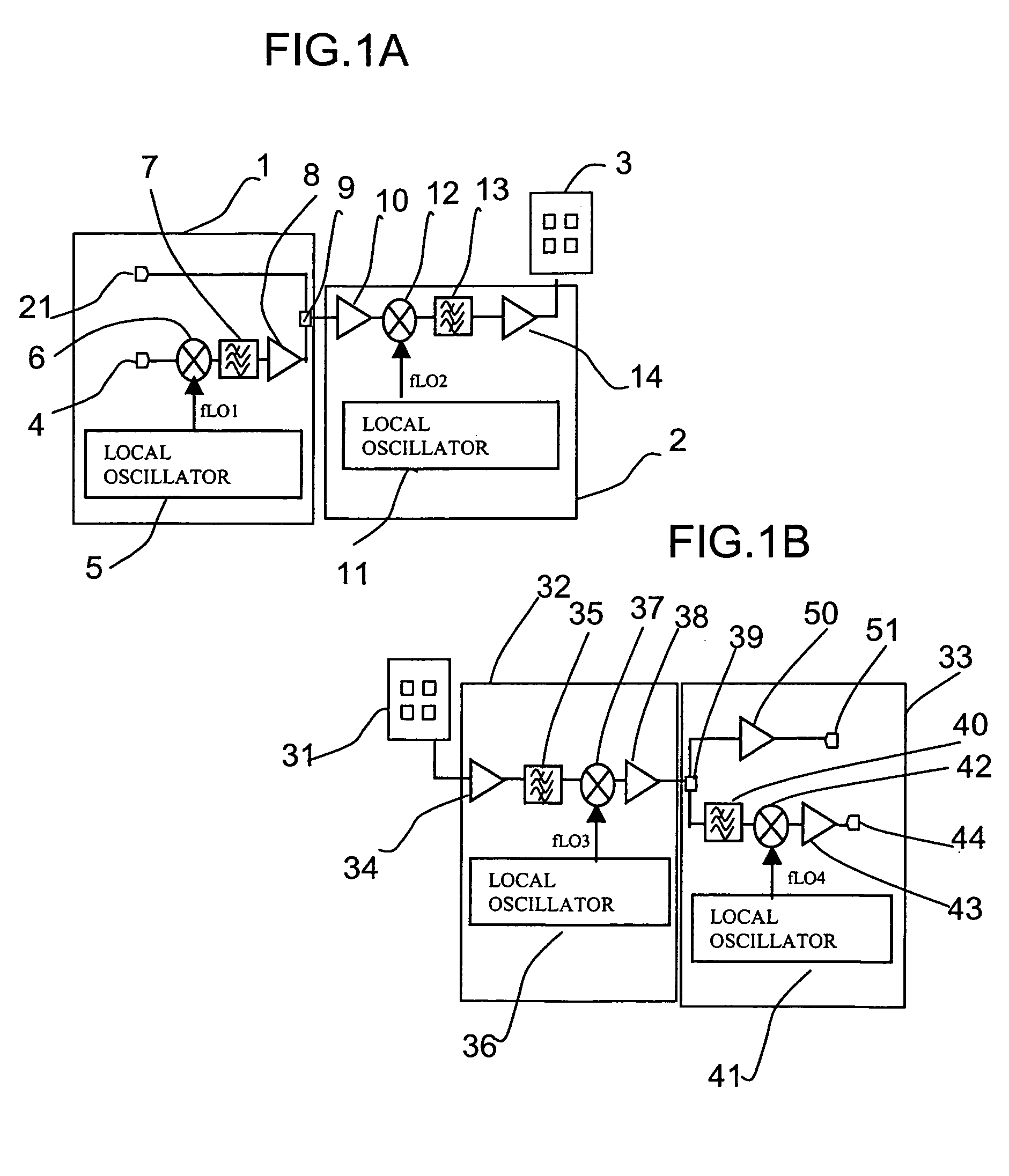
[0053]A millimeter wave band radio communication apparatus according to a first embodiment of the present invention will be described with reference to FIGS. 1A and 1B.

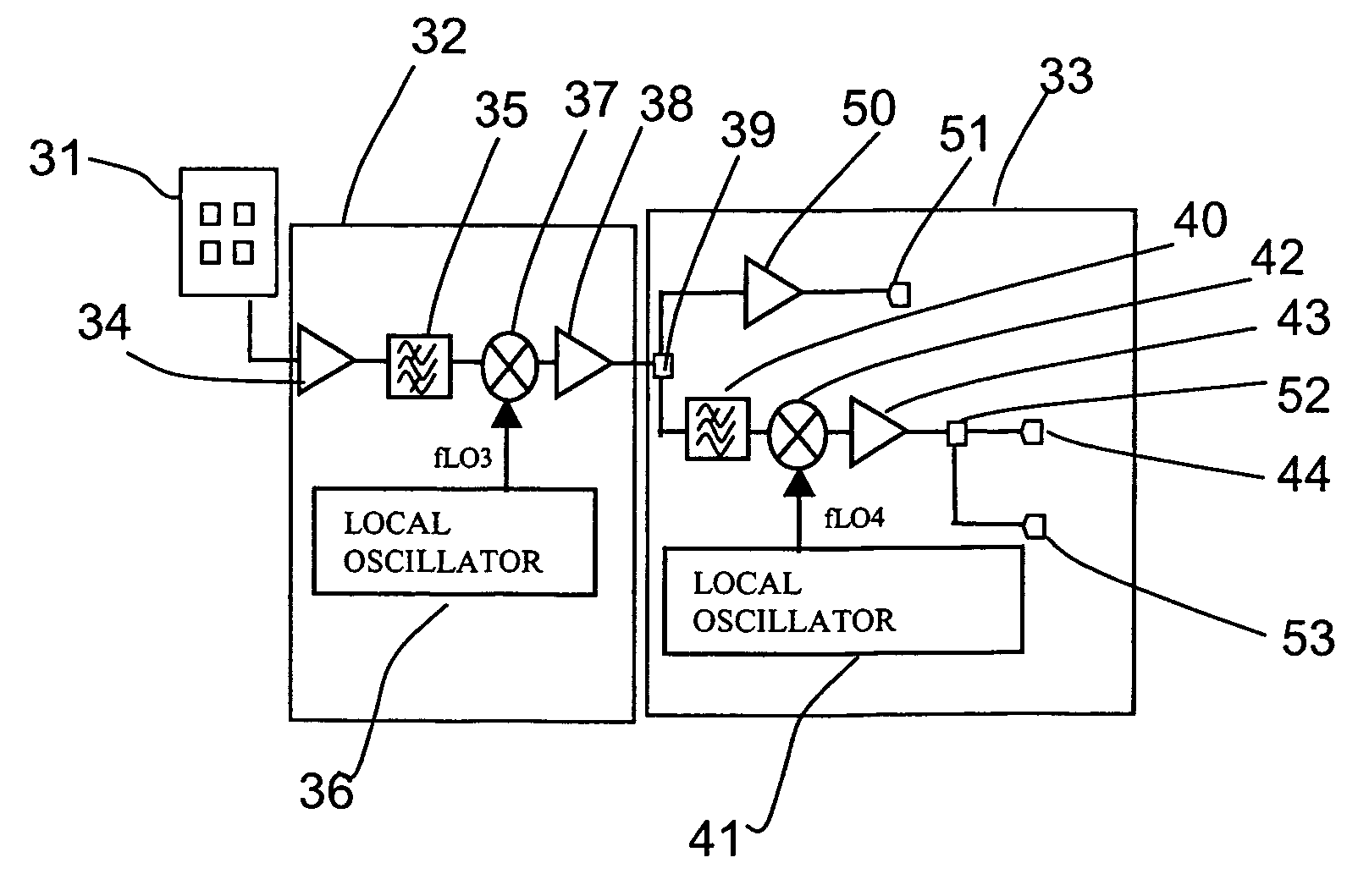
[0054]Referring to FIG. 1A, the millimeter wave band transmitter of the first embodiment basically includes a frequency arranging circuit 1 and a frequency up-converter 2.

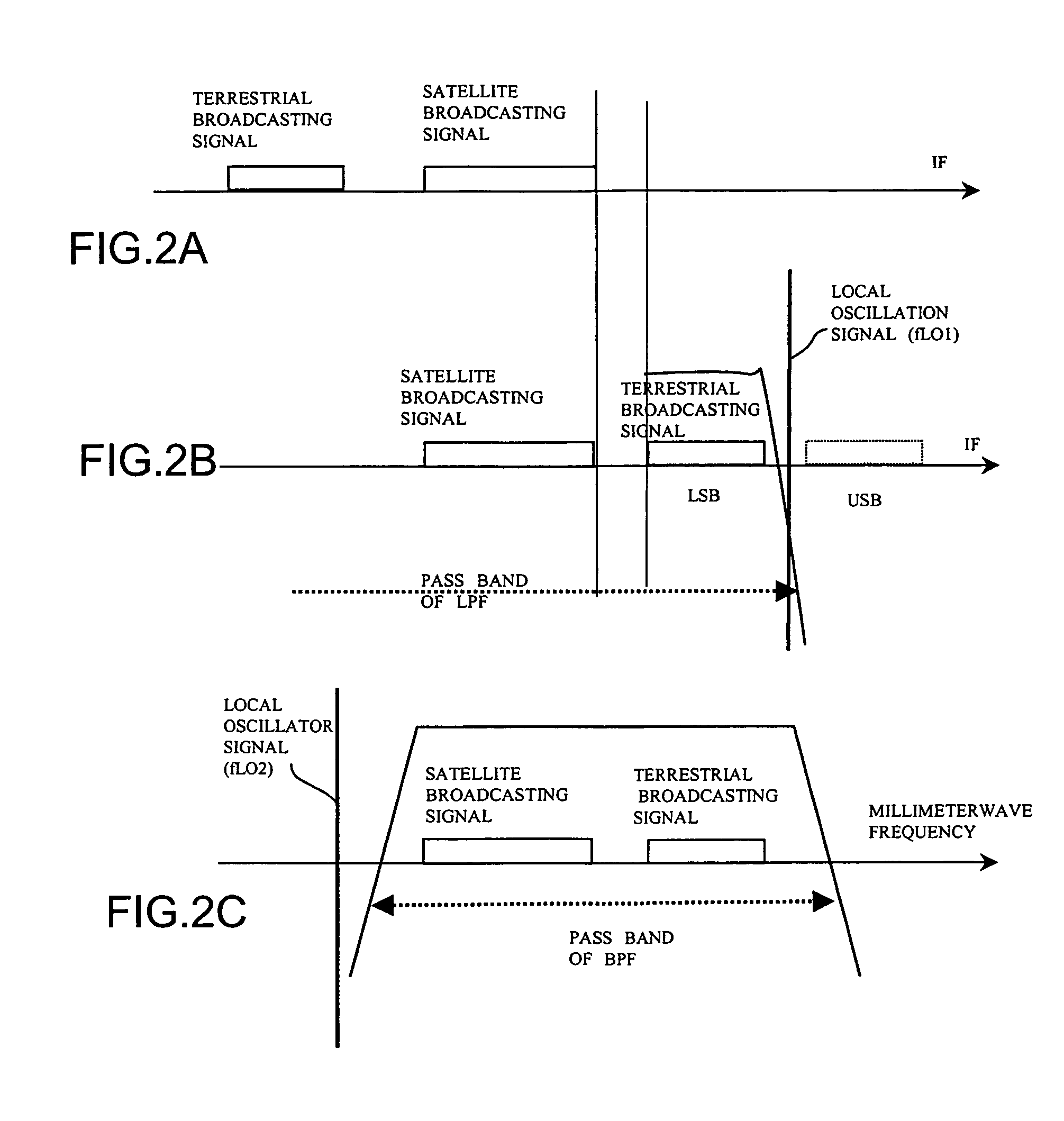
[0055]Frequency arranging circuit 1 includes input terminals 4 and 21 receiving modulation signal waves that are to be transmitted. The first embodiment will be described corresponding to the case where a signal of the UHF band of a terrestrial TV broadcast (referred to as “terrestrial broadcasting signal” hereinafter) is applied to input terminal 4 as a first modulation signal wave and a signal of an intermediate frequency band of a satellite TV broadcast (referred to as “satellite broadcasting signal” hereinafter) is input to input terminal 21 as a second modulation signal wave, by way of example. FIG. 2A shows the arrangement o...

second embodiment

(2) Second Embodiment

[0070]A millimeter wave band radio communication apparatus according to a second embodiment of the present invention will be described with reference to FIGS. 3A and 3B.

[0071]The millimeter wave band transmitter of the second embodiment shown in FIG. 3A is similar to the millimeter wave band transmitter of the first embodiment shown in FIG. 1A except for the following points.

[0072]In contrast to the millimeter wave band transmitter of FIG. 1A in which a terrestrial broadcasting signal and a satellite broadcasting signal are applied to input terminals 4 and 21 as first and second modulation signal waves, respectively, the millimeter wave band transmitter of FIG. 3A also includes an input terminal 22 receiving a third modulation signal wave in frequency arranging circuit 1 in addition to the foregoing inputs.

[0073]More specifically, the second embodiment is described corresponding to the case where a terrestrial broadcasting signal is applied to input terminal 4 a...

third embodiment

(3) Third Embodiment

[0093]There is the case where the first modulation signal wave (terrestrial broadcasting signal) restored and output by the receiver cannot be demodulated by a tuner and a demodulator of the proceeding stage (not shown) if the stability of local oscillation frequencies fLO1 and fLO4 of local oscillators 5 and 41 is low in the millimeter wave band communication apparatus of the first and second embodiments.

[0094]The third embodiment of the present invention is directed to improve stability of local oscillation frequencies fLO1 and fLO4 of local oscillators 5 and 41 to restore the first modulation signal wave output from output terminal 44 at high accuracy.

[0095]A millimeter wave band radio communication apparatus according to the third embodiment of the present invention will be described with reference to FIGS. 5A and 5B.

[0096]The millimeter wave band transmitter of the third embodiment shown in FIG. 5A is similar to the millimeter wave band transmitter of the fi...


PUM


Abstract

A millimeter wave band communication apparatus includes a millimeter wave band transmitter receiving a plurality of input modulation signal waves to transmit a millimeter wave band multiplex signal wave, and a millimeter wave band receiver receiving the transmitted millimeter wave band multiplex signal wave to restore the plurality of input modulation signal waves. The millimeter wave band transmitter includes a frequency arranging circuit generating a multiplex signal wave having respective frequency bands of the plurality of input modulation signal waves arranged on the frequency axis independent of each other, a frequency up-converter up-converting the generated multiplex signal wave to the millimeter wave band, and a transmission circuit transmitting the millimeter wave band multiplex signal wave. The millimeter wave band receiver includes a reception circuit receiving the millimeter wave band multiplex signal wave, a frequency down-converter down-converting the millimeter wave band multiplex signal wave from the millimeter wave band, and a frequency rearranging circuit restoring the down-converted multiplex signal wave into the plurality of input modulation signal waves respectively having the former frequency bands.

Description

BACKGROUND OF THE INVENTION[0001]1. Field of the Invention[0002]The present invention relates to millimeter wave band transmitters, millimeter wave band receivers and millimeter wave band communication apparatuses. More particularly, the present invention relates to a millimeter wave band transmitter, a millimeter wave band receiver and a millimeter wave band communication apparatus that can multiplex a plurality of modulation signal waves to perform radio communication in a millimeter wave band region.[0003]2. Description of the Background Art[0004]A conventional radio communication apparatus for radio communication in an UHF (Ultra High Frequency) band region is used in practice. The need arises for a radio communication apparatus that allows radio communication at a millimeter wave band region which is a higher frequency wave band region, based on the conventional radio communication apparatus of the UHF band without improvement of the communication apparatus per se.[0005]Japanes...

Claims


Application Information

Patent Timeline
Patent Type & Authority Patents(United States)
IPC IPC(8): H03J1/00H04B1/16H04B1/26H04B1/40H04B1/04H04J1/00H04J1/04H04J1/08H04M1/00
CPCH03J1/005H04J1/04H04J1/08
Inventor SUEMATSU, EIJI
Owner SHARP KK
Why Eureka
Try Eureka