System and method for bi-directional mapping between customer identity and network elements

a customer identity and network element technology, applied in the field of object-oriented applications, can solve the problems of service provider's inability to relate the failure of a network element and persist, and achieve the effect of facilitating bill preparation

Inactive Publication Date: 2005-12-06
AT&T INTPROP 1 L P A OF NEVADA
View PDF11 Cites 20 Cited by
  • Summary
  • Abstract
  • Description
  • Claims
  • Application Information

AI Technical Summary

Benefits of technology

[0013]The system of the present invention may be used, for example, to identify which customers rely on a certain network element. The system may also be used, in a reverse manner, to identify all the network elements that support a certain customer. The present invention has several customer service benefits that derive from such network topology maps, whether developed from a customer, service, or managed network point of view. For example, the present invention may be employed by customer service personnel to identify customers affected by a network element failure. Once identified, customer service personnel can notify the customer of a maintenance or operational problem, or save a per-customer record of the event for subsequent Quality of Service (QoS) or service level agreement calculations. The present invention may also be employed, for example, at a service level where a network element provides multiple services. In this example, the present invention can be used to identify the network elements that support a certain service. This aspect of the present invention, in particular, facilitates bill preparation.
[0014]In addition to the customer service benefits, the present invention may also yield benefits from a network management standpoint. For example, the present invention uses a consistent framework to provide the desired bidirectional mapping for all products in the managed network, regardless of the equipment vendor, thereby providing a vendor independent solution to the customer-to-network mapping issue. Where the service provider controls the mapping process, the present invention gives service providers the freedom to select the form and amount of customer identification information used in the mapping process. Lastly, service providers can easily tailor the framework to accommodate a network of any size.

Problems solved by technology

One pervasive problem affecting QoS is a service provider's inability to relate the failure of a network element, such as a switch, to the customer or customers serviced by that element.
Another problem is identifying all the network elements that service a particular customer.
A few vendors have offered vendor-specific solutions, but the problem persists among service providers that use equipment from many different vendors.

Method used


Image

  • System and method for bi-directional mapping between customer identity and network elements
  • System and method for bi-directional mapping between customer identity and network elements
  • System and method for bi-directional mapping between customer identity and network elements

Examples


Embodiment Construction

[0024]It is to be understood that the figures and descriptions of the present invention have been simplified to illustrate elements that are relevant for a clear understanding of the present invention while eliminating, for purposes of clarity, other elements. For example, certain system details and modules of certain intelligent platforms are not described herein. Those of ordinary skill in the art will recognize, however, that these and other elements may be desirable in a typical network. A discussion of such elements is not provided because such elements are well known in the art and because they do not facilitate a better understanding of the present invention.

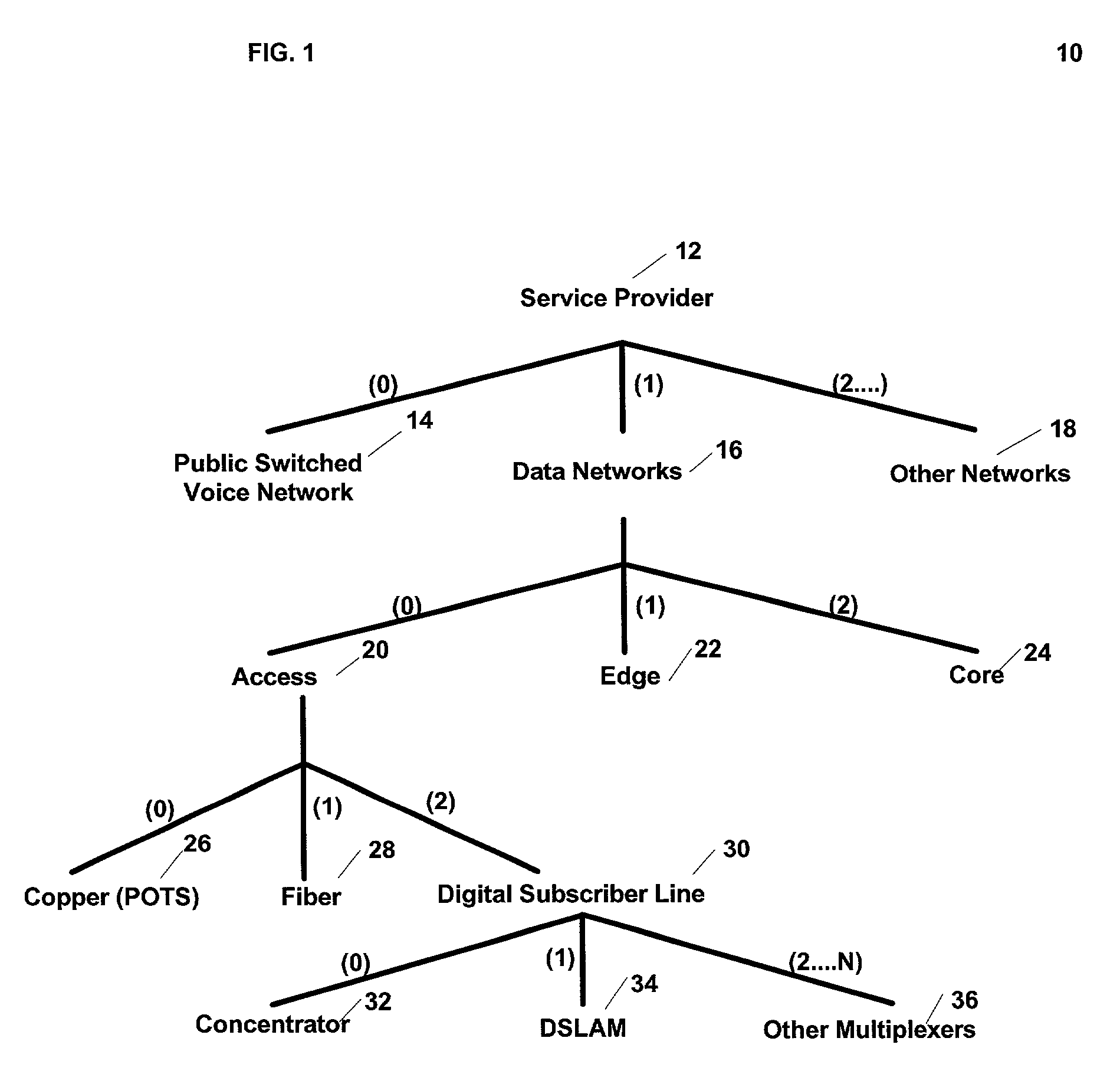
[0025]FIG. 1 illustrates an exemplary relational structure of objects stored in a network element database. In the network illustrated in FIG. 1, service provider 12 has the following subclasses: public switched voice network 14, data networks 16, and a collection of other networks 18. The subclasses may also be defined i...


PUM


Abstract

Systems and methods for relating network elements to customers in a communications network using an object-oriented relational structure. The present invention is directed to systems and methods for relating network elements to customers in a communications network using an object-oriented relational structure. According to one embodiment, the object-oriented system, for relating network elements to a customer or for relating a customer to the network elements, includes a network element data module containing network element data arranged in a form that can be manipulated using an object-oriented application; a customer data module; and a mapping module in communication with the network element data module and the customer data module for creating an object-oriented model of the network elements. The output of the mapping module comprises a plurality of sub-tree layers wherein each layer represents a layer of abstraction, and wherein a root represents the highest sub-tree layer and the highest level of abstraction and a plurality of unique customer identifiers assigned to network elements that relate the customer to certain network elements.

Description

CROSS REFERENCE TO RELATED APPLICATIONS[0001]Not Applicable.STATEMENT REGARDING FEDERALLY SPONSORED RESEARCH OR DEVELOPMENT[0002]Not Applicable.BACKGROUND OF THE INVENTION[0003]1. Field of Invention[0004]The present invention relates generally to object-oriented applications and, more particularly, to systems and methods for relating network elements to customers in a communications network using an object-oriented relational structure.[0005]2. Description of the Background[0006]Providers of communication services are investing in and deploying the latest generation of network equipment in an attempt to maximize network functionality in an increasingly competitive market. Such growth has exerted pressure on service providers to maintain or even improve Quality of Service (QoS). One pervasive problem affecting QoS is a service provider's inability to relate the failure of a network element, such as a switch, to the customer or customers serviced by that element. A customer, in this c...

Claims


Application Information

Patent Timeline
Patent Type & Authority Patents(United States)
IPC IPC(8): H04L12/24
CPCH04L41/0233Y10S707/99945Y10S707/99948
Inventor WEISSER, JR., DECEASED, FRANK J.WEISSER, LEGAL REPRESENTATIVE, PHYLLIS C.
Owner AT&T INTPROP 1 L P A OF NEVADA
Why Eureka
Try Eureka