
Encoder

a technology of encoder and rotary member, which is applied in the direction of counting mechanisms/objects, measuring devices, instruments, etc., can solve the problems of high-cost production process such as precise etching or laser processing, and the rotation direction of the rotary member may be erroneously detected, so as to prevent the malfunction of the detection circuit and detect high accuracy

Inactive Publication Date: 2005-12-13
ALPS ALPINE CO LTD
View PDF15 Cites 9 Cited by
  • Summary
  • Abstract
  • Description
  • Claims
  • Application Information

AI Technical Summary

Benefits of technology

The present invention provides an encoder that can detect high accuracy and prevent malfunctions even if the electrode pattern is not perfectly formed. It is also suitable for miniaturization. The encoder includes a fixed member, a rotary member, and a click mechanism for stabilizing the rotary member. The rotary member has electrode patterns and contacts that switch between a conductive state and a non-conductive state when the rotary member is rotated. The state between the electrodes switches at each rotation of the rotary member for a predetermined click angle. This ensures high accuracy and prevents malfunctions of the detection circuit.

Problems solved by technology

Therefore, the pattern of the electrode 105 need be precisely processed, which results in the necessity of providing a high-cost production process such as precise etching or laser processing.
Therefore, the rotating direction of the rotary member may be erroneously detected once a slight scratch is made on the electrode 105 by sliding contact with the sliders.

Method used


Image

  • Encoder
  • Encoder
  • Encoder

Examples


Embodiment Construction

[0034]The present invention will be discussed hereinafter in detail in terms of the preferred embodiment according to the present invention with reference to the accompanying drawings. In the following description, numerous specific details are set forth in order to provide a thorough understanding of the present invention. It will be obvious, however, to those skilled in the art that the present invention may be practiced without these specific details. In other instance, well-known structures are not shown in detail in order to avoid unnecessary obscurity of the present invention.

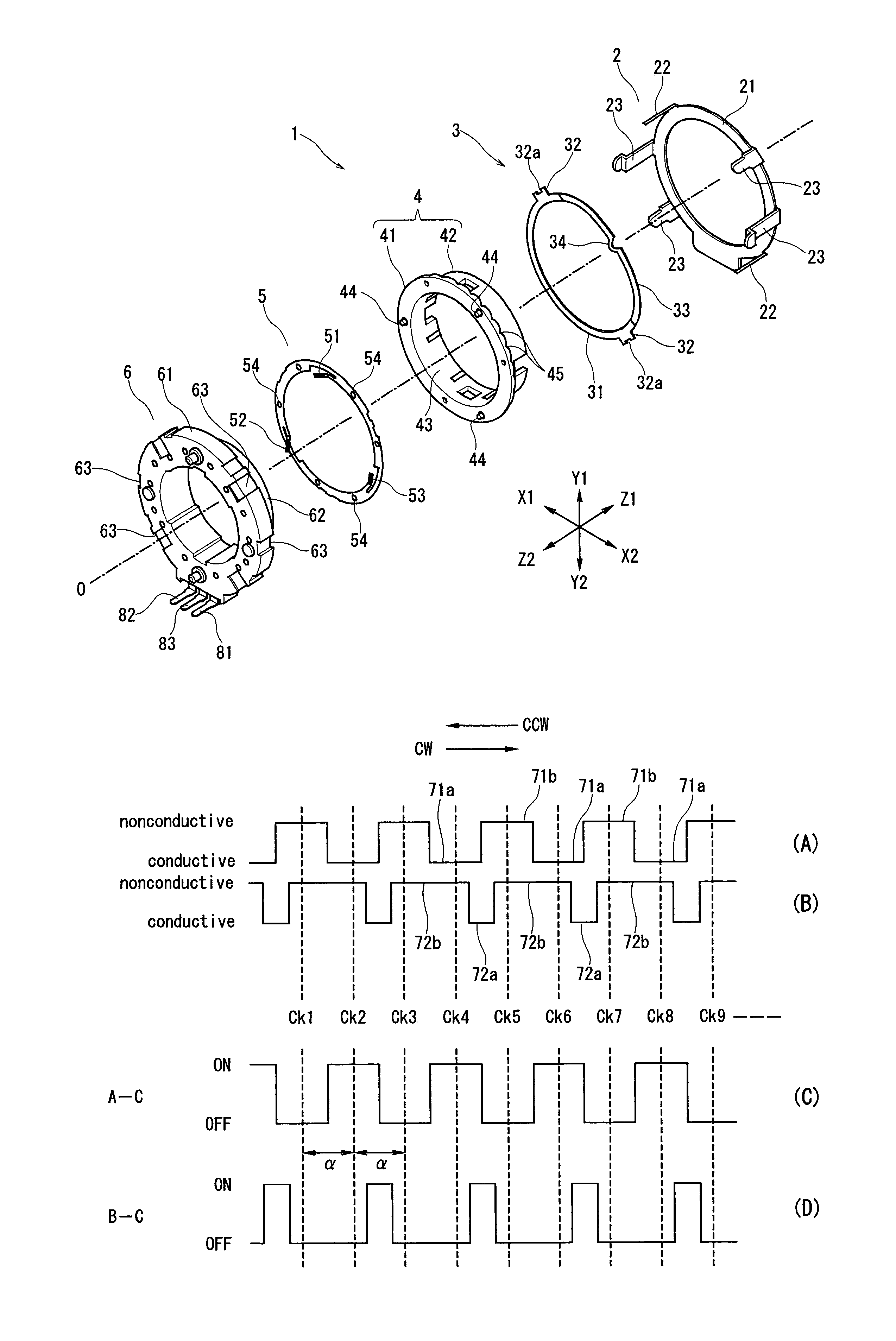
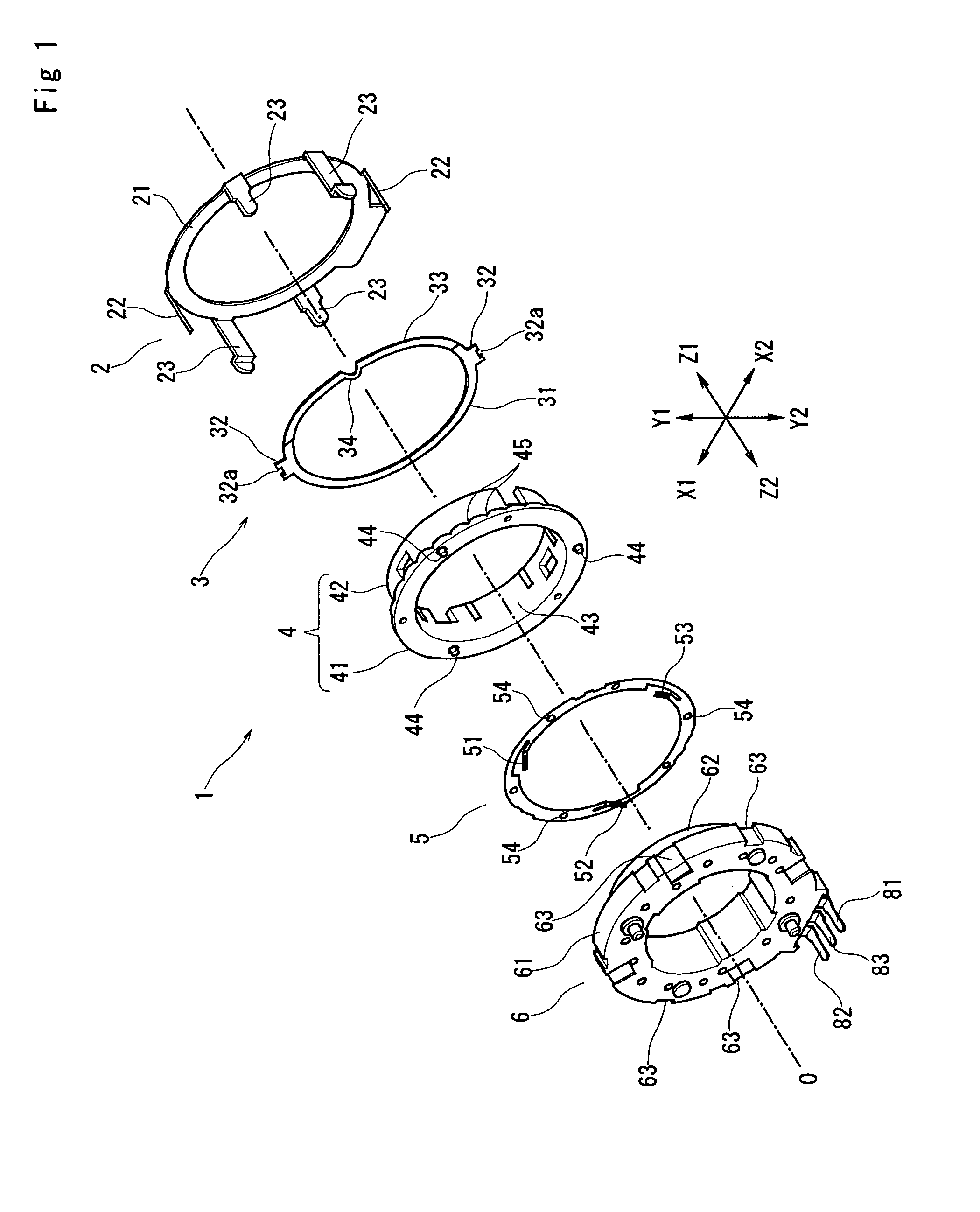
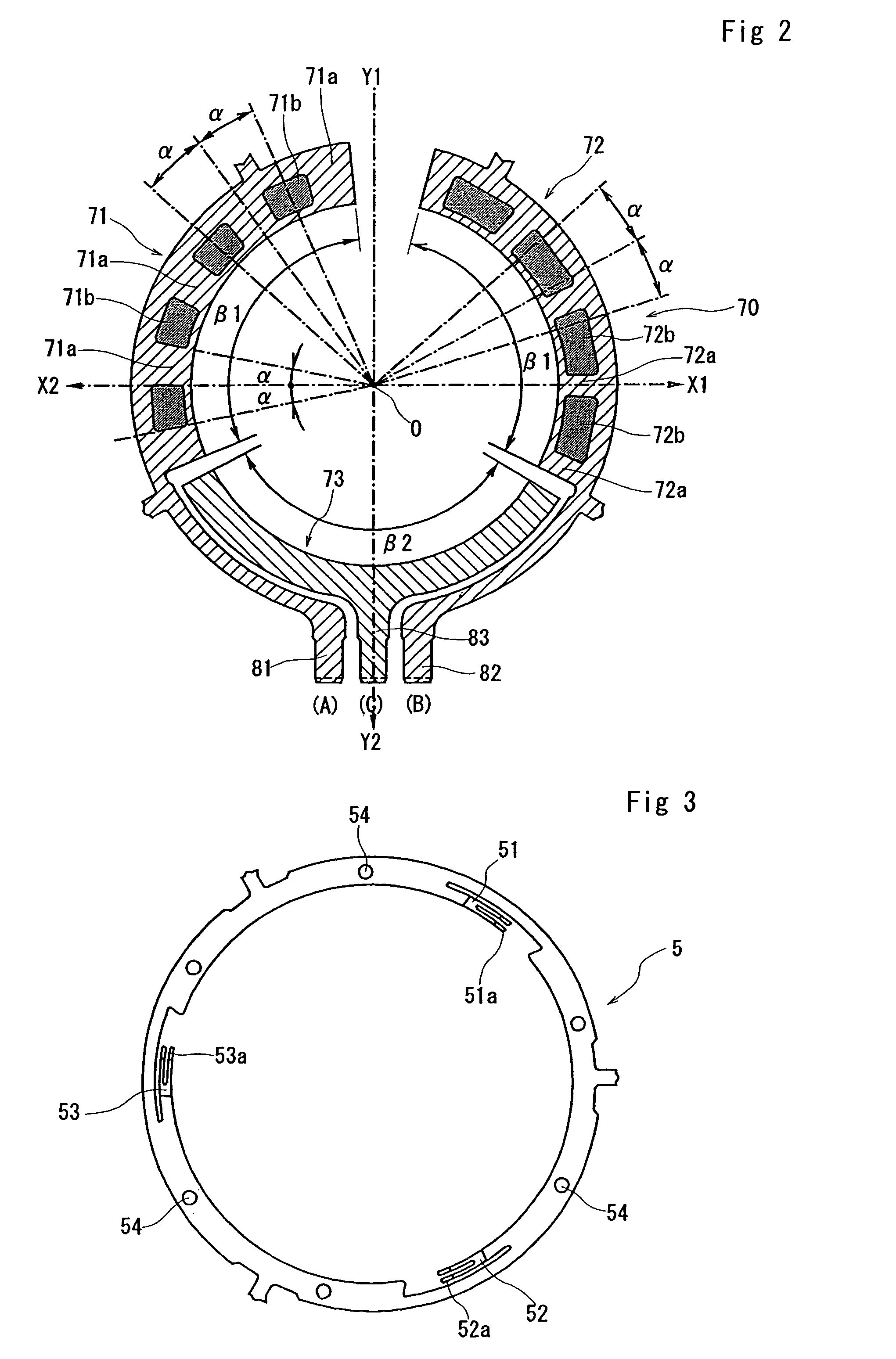
[0035]FIG. 1 is an exploded perspective view of an encoder according to one embodiment of the present invention; FIG. 2 is a front view showing a pattern of an electrode provided at a fixed side; FIG. 3 is a front view showing a sliding member; FIGS. 4 and 5 are front views for describing operation of the encoder; FIG. 6 is a timing diagram illustrating the operation of the encoder; and FIG. 7 is a block ...


PUM


Abstract

Disclosed is an encoder including a rotary member and a fixed member. The fixed member is provided with an electrode having A-channel, B-channel and C-channel patterns, the rotary member is provided with contacts which are to be opposed to the electrode. A-C state switches from OFF to ON at each rotation of the rotary member for one click angle from a stable click position in both CW and CCW direction. During CW rotation for one click angle, B-C state remains unchanged from OFF; during CCW rotation for one click angle, B-C state switches twice between ON and OFF.

Description

BACKGROUND OF THE INVENTION[0001]1. Field of the Invention[0002]The present invention relates to an encoder, in which as a rotary member is rotated, a state between A-channel and C-channel and a state between B-channel and C-channel switch between a conductive state and a nonconductive state, and more particularly, relates to an encoder, in which even if small-sized, a pattern of electrode can be easily formed for A-channel, B-channel and C-channel.[0003]2. Description of the Related Art[0004]FIG. 8 is an explanatory drawing showing a summary of a construction of a conventional rotary encoder, and FIG. 9 shows wave-form charts (A) and (B) of output from the encoder. For example, an encoder of this kind is disclosed in Japanese Patent No. 2506877.[0005]Conductive sliders 102, 103 and 104 are provided opposite a surface of a disk-shaped substrate 100. On the surface of the substrate 100, a disk-shaped electrode 105, which is formed of a conductive material such as gold, silver and cop...

Claims


Application Information

Patent Timeline
Patent Type & Authority Patents(United States)
IPC IPC(8): G01D5/252G01D5/244G01D21/00G06M1/27
CPCG01D5/252
Inventor AIKAWA, KAZUOHAYASHI, HIDEYASU
Owner ALPS ALPINE CO LTD
Learn More