Shielded structure for radiation treatment equipment and method of assembly

a radiation treatment equipment and shielding technology, applied in the field of structure and method for constructing a structure for housing a therapeutic radiation source, can solve the problems of high cost of constructing these buildings, severe limitations on the feasibility of radiation treatment centers in many locations, and inability to easily disassemble or remodel centers

Inactive Publication Date: 2005-12-13
RAD TECH MEDICAL SYST LLC
View PDF43 Cites 52 Cited by
  • Summary
  • Abstract
  • Description
  • Claims
  • Application Information

AI Technical Summary

Benefits of technology

[0010]There is also provided an apparatus for selectively blocking radiation through a doorway comprising a door and a retractable threshold adjacent the door, wherein the door and the retractable threshold each comprise radiation shielding material, a lifting mechanism for raising the threshold when the door is closed and lowering the threshold when the door is open, wherein the threshold blocks radiation leakage under the door when the door is closed and permits substantially unobstructed access through the doorway when the door is open. In further refinements a portion of the threshold is above the bottom of the door when the door is closed, and the threshold retracts substantially under its own weight when the door is opened.

Problems solved by technology

However, the need for shielding, which is traditionally provided by concrete walls or mounds of dirt, severely limits the feasibility of radiation treatment centers in many locations.
This limitation is due at least in part to the high cost of constructing these buildings and to the inability to easily disassemble or remodel the centers to accommodate new development of the surrounding structures and land.

Method used


Image

  • Shielded structure for radiation treatment equipment and method of assembly
  • Shielded structure for radiation treatment equipment and method of assembly
  • Shielded structure for radiation treatment equipment and method of assembly

Examples


Embodiment Construction

[0040]For the purposes of promoting an understanding of the principles of the invention, reference will now be made to the embodiment illustrated in the drawings and specific language will be used to describe the same. It will nevertheless be understood that no limitation of the scope of the invention is thereby intended, such alterations and further modifications in the illustrated structures and methods, and such further applications of the principles of the invention as illustrated therein being contemplated as would normally occur to one skilled in the art to which the invention relates.

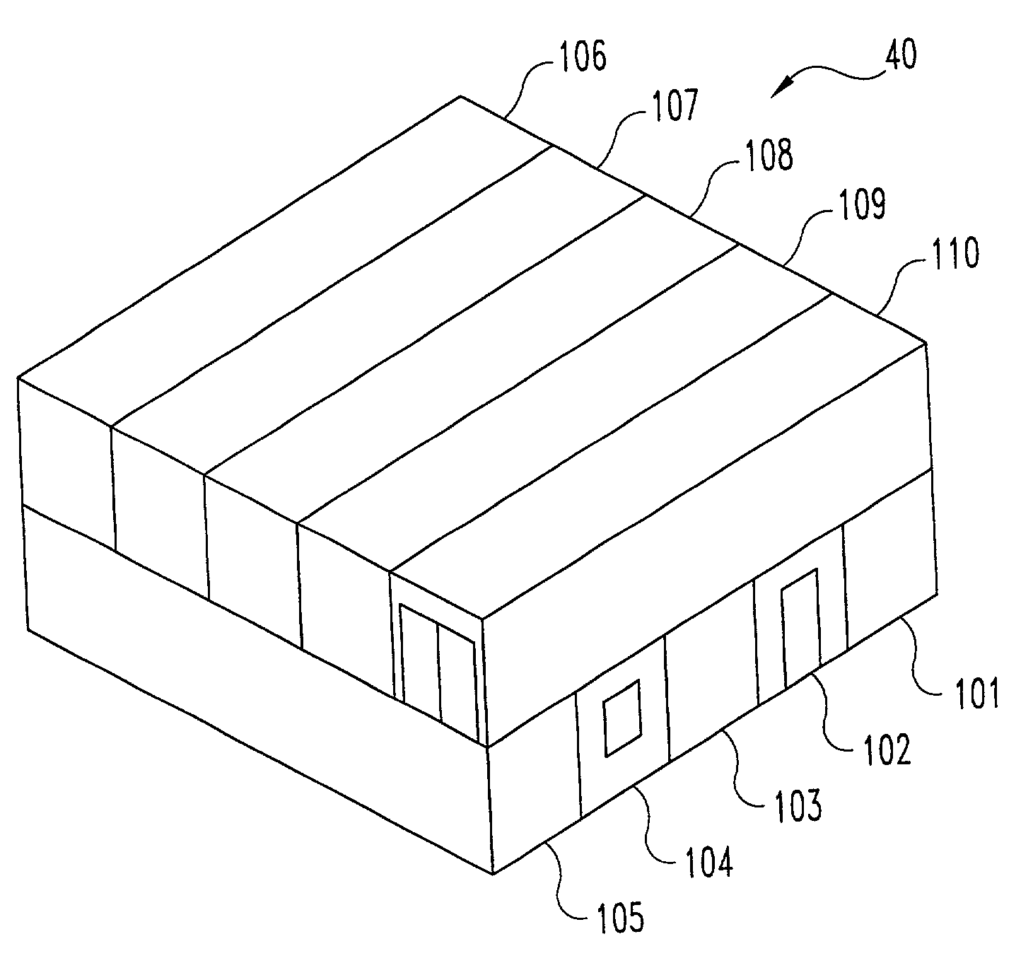
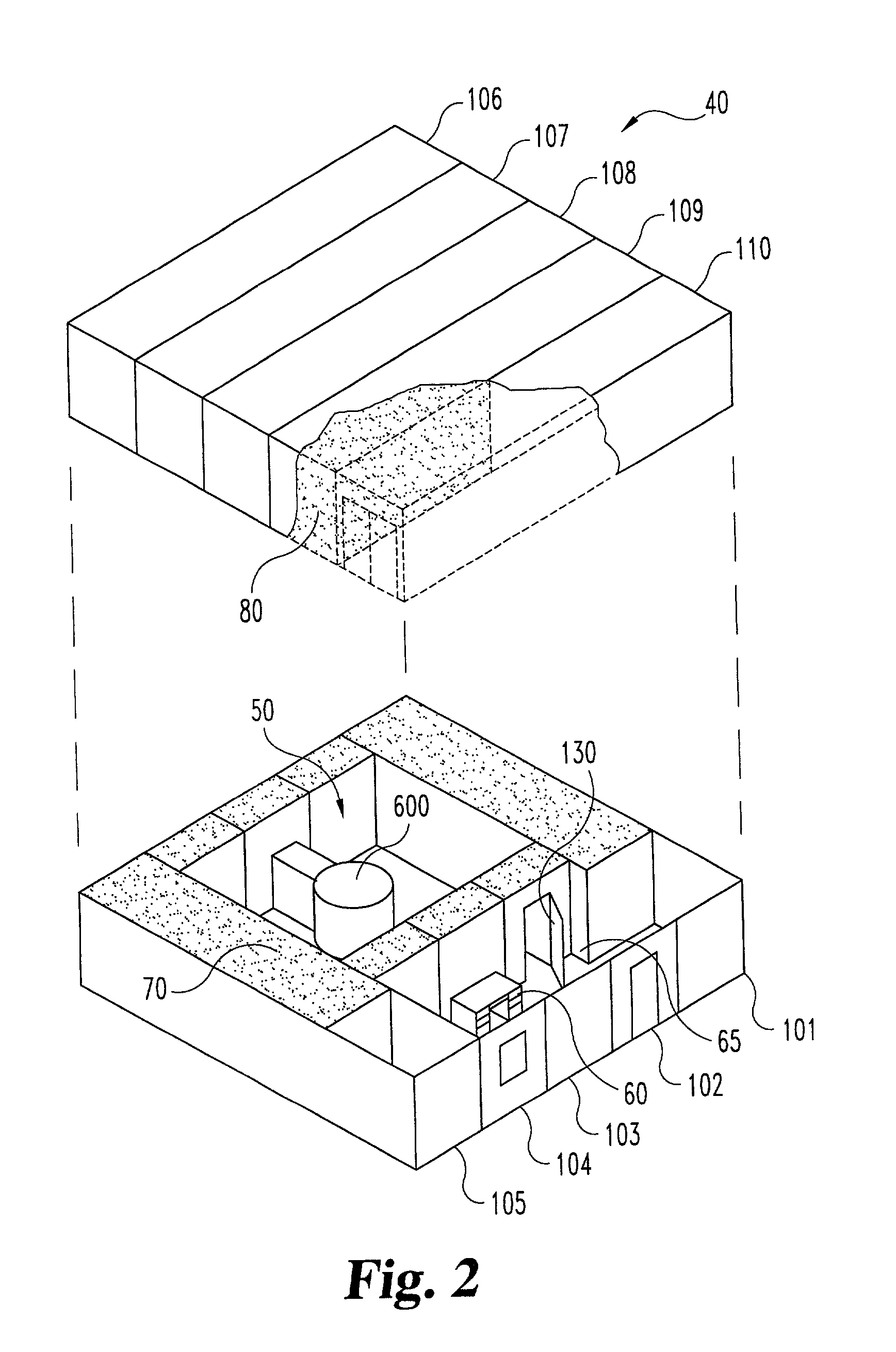
[0041]Turning now to FIGS. 1 and 2, structure 40 for housing therapeutic radiation equipment is depicted. Structure 40 is a modular unit that is assembled to form a radiation therapy vault room 50, and can be delivered to a site in sections with all equipment and finishings in place. The individual sections 101–110, herein referred to as pods or modules, are preferably each capable of being shipp...


PUM


Abstract

A structure that can be partially assembled at one location, transported to a site in modules, and then fully assembled into a structure suitable for housing a therapeutic radiation source is disclosed. The modules include reinforced walls that are filled with radiation shielding fill material to form a barrier around a central treatment area. Additional modules are placed over the first set of modules and form a barrier above the treatment room. A door with a selectively retractable threshold provides access to the treatment room. The module including the radiation equipment is included in removable portions so that the radiation equipment can be removed and replaced. The modules also form a patient waiting room and control area separated from the treatment by the barrier.

Description

FIELD OF THE INVENTION[0001]The present invention relates generally to structures and portions thereof for housing radiation sources and shielding humans working near those sources. More particularly but not exclusively the present invention relates to a structure and method for constructing a structure for housing a therapeutic radiation source.DESCRIPTION OF THE RELATED ART[0002]Radiation is used in the diagnosis and treatment of patients in various ways. However, while controlled doses can be beneficial to a patient, those working with the radiation or merely in the surrounding area need to be protected from the harmful effects of the radiation. Accordingly, shielding is traditionally provided to isolate the radiation source from those in the surrounding area and provide some protection from the levels associated with normal use of the equipment and also, to some extent, to accidents with the radiation equipment.[0003]However, the need for shielding, which is traditionally provid...

Claims


Application Information

Patent Timeline
Patent Type & Authority Patents(United States)
IPC IPC(8): G21F7/00A61N5/10E04B1/348E04H1/12E04H3/08G21F3/04G21K5/00
CPCE04B1/3483E04H1/1205E04H1/125E04H1/1277E04H3/08G21F3/04A61N5/10A61N2005/1094E04H2001/1283E04B1/92E04B2001/925
Inventor ZEIK, GARYLANDAU, ERICGARRISON, JOE DONOQUIST, CHERI ANNMCCARTHY, RONALD C.ENGELHART, THEODORE M.
Owner RAD TECH MEDICAL SYST LLC
Why Eureka
Try Eureka