
Slurry fertilizer applicator

a fertilizer applicator and slurry technology, applied in the direction of direct liquid fertilizer delivery, furrow making/covering, agriculture, etc., can solve the problems of less and less acceptable procedures, strong odor after waste spread, and inability to achieve the effect of reducing the application rate of slurry fertilizer and minimizing soil disturban

Active Publication Date: 2005-12-13
DEEP SPACE INDUSTRIES
View PDF5 Cites 23 Cited by
  • Summary
  • Abstract
  • Description
  • Claims
  • Application Information

AI Technical Summary

Benefits of technology

"The present invention is a new and improved slurry fertilizer applicator designed for use at high speeds (5-8 mph) and with reduced application rates. It employs a spring-cushioned colter and a curved mounting shank to cut an initial slot in residue and provide a vertical parting line in the soil. The sweep shank is thin and mounted to the mounting shank by two vertically spaced bolts, allowing for quick clearance of obstacles. The sweep shank is designed to minimize soil disruption and has a nose portion with a lower portion that breaks the soil and parts it at the operating depth. The sweep shank also has fissures that allow slurry to flow into the narrow furrow formed by the sweep shank without lifting or binding with other parts of the applicator. The slurry discharge tube is pivotally mounted to the sweep shank and a slurry distribution tube is provided to extend the lateral distribution of slurry and reduce high concentrations of slurry. The applicator allows for high-speed operation without soil displacement and is designed to minimize damage to the soil surface."

Problems solved by technology

This procedure has, as a principle objection, a strong odor which remains after the waste is spread.
Moreover, surface spreading of animal waste is not desirable with the potential runoff of nitrates and phosphorus into rivers and streams or seeping of the material into ground water sources.
This is objectionable because livestock waste is high in nitrogen, and swine waste is also high in phosphorus, and with increasing concern with the quality of drinking water, this procedure is becoming less and less acceptable.
This method, however, has not fully overcome the concentration problem, and it presents still another problem—namely, the cultivator sweep unnecessarily tills the soil and may result in burying surface residue.
This may be a separate problem, particularly for farmers whose land may have been designated HEL, because there are federal requirements to maintain a certain percentage of crop residue on the surface of such soil.
However, the ground speed of the '131 patent is limited to a range of 3–5 miles per hour.
Any greater speed would cause too much soil disruption, lifting and redistribution (i.e. tillage) due to the use of a forward portion of the shoe which acts like a plow point, having a surface which is inclined upwardly and rearwardly for fracturing and lifting the soil in front of the shank.
At higher speeds the '131 device acts like the shank of a chisel plow, not only creating substantial turbulence in the soil, but burying surface residue, which, in certain applications mentioned above is undesirable.

Method used


Image

  • Slurry fertilizer applicator
  • Slurry fertilizer applicator
  • Slurry fertilizer applicator

Examples


Embodiment Construction

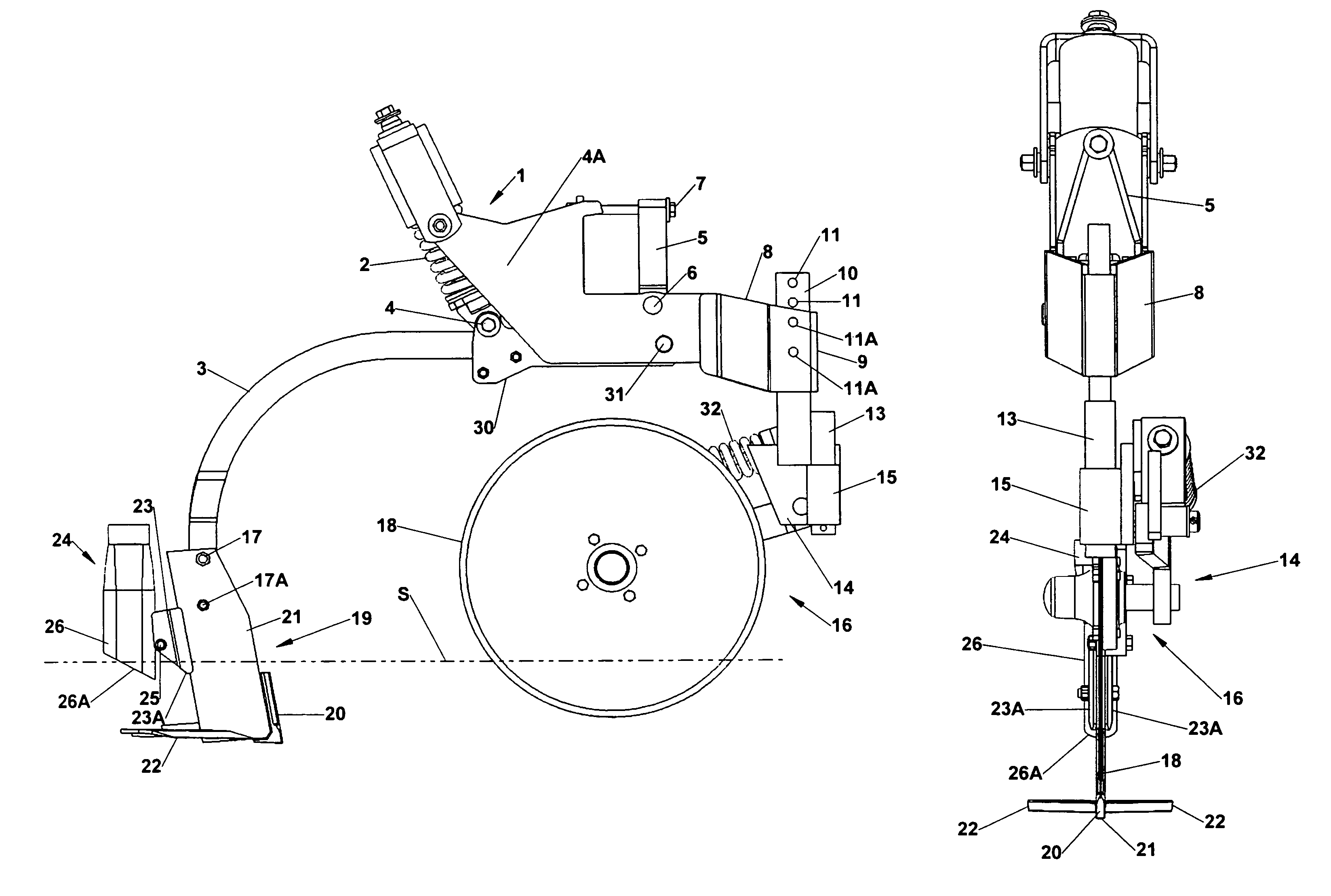
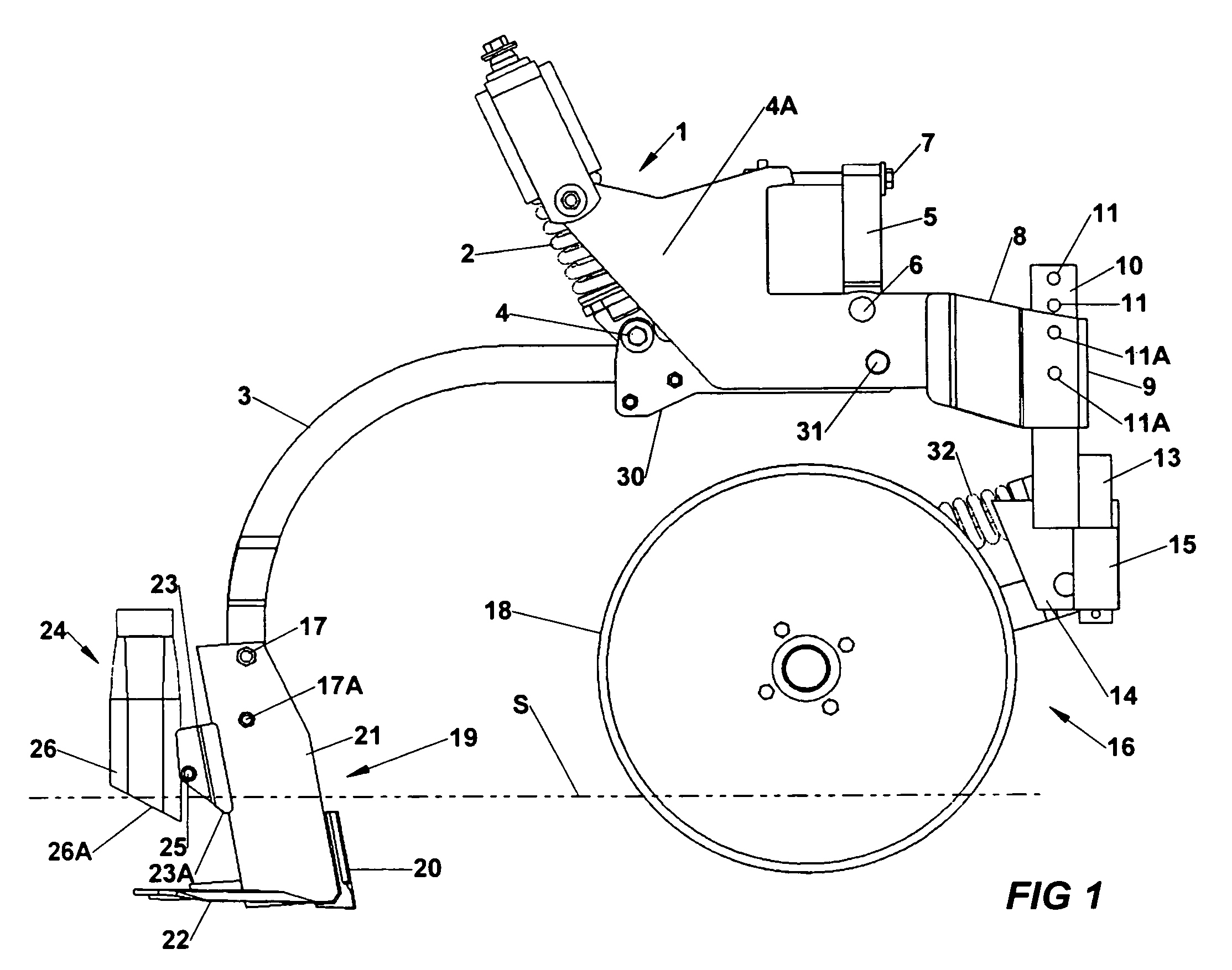
[0028]Referring to FIG. 1, a left side view of the overall applicator unit. Reference numeral 1 generally designates a spring reset mechanism for a single row unit of a slurry applicator. As is known, a number of such applicator units are mounted on a wagon or tool bar drawn by a tractor. The applicator units are mounted in side-by-side relation, and spaced apart. The tool bar or frame may have its own support wheels, or be mounted to a wagon carrying the slurry. In any case, it trails a slurry wagon or container for a large amount of slurry fertilizer which is to be applied to a field. A spring 2 is compressed (i.e. preloaded) and pivotally connected to a main mounting shank 3 by a bolt 4. When a rock or other obstruction is encountered by the sweep 19, the main shank 3, applicator sweep 19 and slurry tube 24 are pivoted up and away from the obstruction.

[0029]The spring cushion mechanism is mounted to a conventional toolbar by shank mount 4A and a bracket 5 that pivots on bolt 6. W...


PUM


Abstract

An applicator unit for applying slurry fertilizer beneath the soil with reduced soil displacement includes a spring-cushioned main mounting shank and a forward spring-biased colter. A narrow applicator shank is mounted to the main mounting shank by a pair of vertically spaced bolts, including a lower shear bolt, at a location just above the surface of the soil. The sweep shank is generally upright and includes a nose portion at a lower leading edge which includes a generally blunt lower portion and a tapered leading edge for forming a furrow without tilling the soil. The furrow is formed in three stages by the blunt nose pad, the upright tapered leading edge of the sweep shank, and by a pair of mounting plates carrying the slurry tube and widening the top of the furrow.

Description

RELATED APPLICATIONS[0001]This application claims the benefit under 35 U.S.C. 120 of co-pending U.S. Provisional Application 60 / 532,497 for “SLURRY FERTILIZER APPLICATOR” filed Dec. 23, 2003.FIELD OF THE INVENTION[0002]The present invention relates to agricultural fertilizer applicators; and more particularly, it relates to apparatus for subsoil application of livestock waste in the form of a slurry (that is, a freely flowable mixture of liquids and solids).BACKGROUND OF THE INVENTION[0003]Historically, livestock waste, particularly in solid form, has been spread on the surface of the soil by a manure spreader using a flail to fling the material to the rear. A more modern side-discharge spreader also deposits the material on the surface of the soil.[0004]The advent of confinement systems for animals which include pits below the confinement area, produces a large amount of animal waste in a slurry form which must be handled and disposed of. Typically, the slurry is pumped in a large ...

Claims


Application Information

Patent Timeline
Patent Type & Authority Patents(United States)
IPC IPC(8): A01C5/06A01C23/02
CPCA01C5/062A01C23/022
Inventor DIETRICH, SR., WILLIAM J.
Owner DEEP SPACE INDUSTRIES
Learn More