
Multiple roll tape dispenser

a tape dispenser and multi-roll technology, applied in the field of multi-roll tape dispensers, can solve the problems of prior art tape dispensers, undesirable or unsuitable for a specific use, and often not being able to accommodate multiple tape rolls with varying dimensional characteristics

Inactive Publication Date: 2005-12-13
BEL ART PRODS
View PDF28 Cites 14 Cited by
  • Summary
  • Abstract
  • Description
  • Claims
  • Application Information

AI Technical Summary

Benefits of technology

[0007]It is a further object of the invention to provide a multiple roll tape dispenser that can be easily reloaded.
[0008]It is an even further object of the invention to provide a multiple roll tape dispenser that is simple in construction and relatively inexpensive to manufacture.
[0016]According to yet another aspect of the invention, the plurality of cross members further comprises a plurality of inner and outer cross members. The outer cross members define an inner maximum diameter within the spool, so that at least one tape roll has an outer peripheral diameter that is less than the inner maximum diameter formed by the outer cross member. According to yet a further aspect of the invention the spool housing assembly further includes at least one clamping mechanism for releasably securing the spool unit. The at least one end cap includes a detent abutment adapted for cooperation with the clamping mechanism, so as to prevent rotational motion of the spool unit relative to the spool housing assembly. The clamping mechanism further includes a guiding trough for operatively guiding the spool unit into the spool housing assembly.

Problems solved by technology

However, such dispensers often are not capable of accommodating multiple tape rolls having varying dimensional characteristics, such as varying inner diameters.
The roll tape dispensers of the prior art generally suffer from one or more drawbacks and limitations that oftentimes render them undesirable or unsuitable for a specific use.
Generally, these drawbacks and limitations stem from the device structure.
It would be obvious that manufacture of such device is laborious, time consuming and therefore expensive.
Furthermore, this device is generally unsuitable for dispensing of rolls of tape having varying inner diameters as well as varying widths.
However, none of these patents disclose a tape dispenser capable of accommodating tape rolls having varying characteristics, such as varying inner diameter.

Method used


Image

  • Multiple roll tape dispenser
  • Multiple roll tape dispenser
  • Multiple roll tape dispenser

Examples


Embodiment Construction

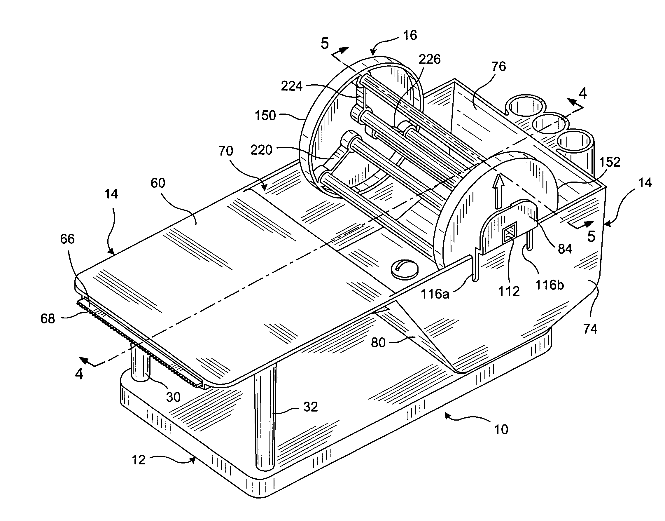
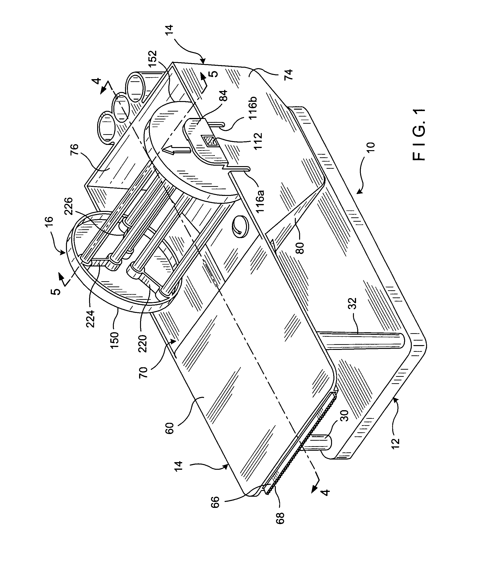
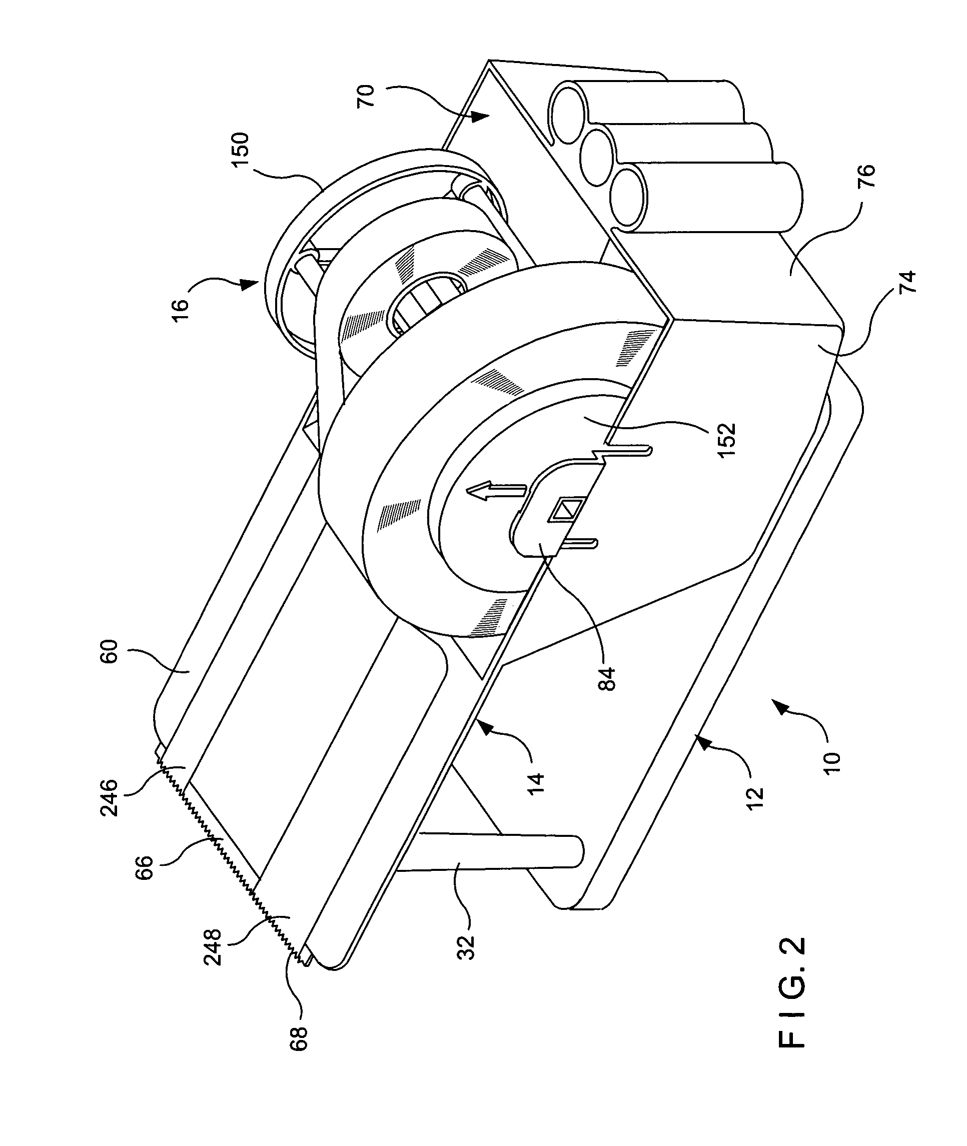
[0034]For purpose of illustration, and not to limit generally, the present invention will now be described with specific reference to FIGS. 1–16. It is noted that the drawings of the invention are intended to depict only typical embodiments of the invention, are not necessarily to scale and are merely schematic representations, not intended to portray specific parameters of the invention. The invention will now be described with additional specificity and detail through the accompanying drawings.

[0035]With reference to the Figures, wherein like numerals reference like or corresponding parts throughout the several views, FIG. 1 shows a representative embodiment of a multiple roll tape dispensing system 10. The multiple roll tape dispensing system 10 includes a base unit 12, a spool housing assembly 14 and a spool unit 16. While the multiple roll tape dispensing system 10 is particularly suitable for dispensing multiple rolls of pressure sensitive adhesive tape, utilization of the sys...


PUM

PropertyMeasurementUnit
diameteraaaaaaaaaa
lengthaaaaaaaaaa
pressureaaaaaaaaaa

Abstract

A multiple roll tape dispenser consists of a spool unit and a spool housing assembly. The spool unit consists of a first end cap connected to a second end cap by at least one inner tape roll supporting cross member for rotatably supporting a first tape roll having a first inner diameter and a plurality of outer tape roll supporting cross members for rotatably supporting a second tape roll having a second inner diameter being greater than the inner diameter of the first tape roll.

Description

FIELD OF THE INVENTION[0001]The present invention relates to multiple roll tape dispensers, and more particularly, to a tape dispensing system capable of simultaneously accommodating a plurality of tape rolls of varying dimensions.BACKGROUND OF THE INVENTION[0002]A typical roll of tape includes a length of tape having an inner tape surface coated with a pressure sensitive adhesive and an outer peripheral tape surface. The length of tape is wrapped around a hollow core, wherein the hollow core defines an inner diameter of the tape roll and the outer peripheral tape surface defines an outer diameter of the tape roll. Rolls of tape come in a variety of shapes and sizes depending upon the length and width of the tape and the diameter of the hollow core.[0003]For nearly every size and shape of tape roll there is a tape dispenser for dispensing varied lengths of tape. In certain situations, however, it is desirable to simultaneously dispense multiple rolls of tape from a single tape dispe...

Claims


Application Information

Patent Timeline
Patent Type & Authority Patents(United States)
IPC IPC(8): B65H35/00B65H35/07
CPCB65H35/0026B65H2301/41342B65H2301/4139B65H2511/10B65H2220/01B65H2220/04Y10T225/241Y10T225/232Y10T225/247Y10T225/282Y10T83/902Y10T225/222
Inventor GOMES, FRANCISLANDSBERGER, DAVIDTHOM, PAUL
Owner BEL ART PRODS
Learn More