Roto-dynamic fluidic systems

a fluidic system and rotational technology, applied in the field of rotational dynamic fluidic systems, can solve the problems of increasing the local velocity of the fluid, lowering the pressure, and disrupting the chemical structure, so as to facilitate cavitation and facilitate cavitation

Inactive Publication Date: 2005-12-13
GARRETT III NORMAN H
View PDF39 Cites 78 Cited by
  • Summary
  • Abstract
  • Description
  • Claims
  • Application Information

AI Technical Summary

Benefits of technology

[0007]Embodiments, among others, of the present invention provide an apparatus and method for facilitating cavitation in a fluid.
[0008]Briefly described, in architecture, one embodiment of the apparatus, among others, can be implemented as follows. The apparatus includes a housing that has a generally hollow interior for receiving a rotor. A rotor having an exterior surface is disposed in the housing, and the rotor defines a first opening disposed on the exterior surface and a second opening with a fluid passage extending therebetween. The fluid passage facilitates cavitation in a fluid.

Problems solved by technology

This collision creates forces that can be disruptive to the chemical structure of the fluid.
The restrictive portion of the venturi creates the necessary local velocity increase and corresponding pressure drop, which precipitates cavitation.
In the case of a venturi, the restriction causes an increase in the fluid's local velocity and thus lowers its pressure.
These bubbles collapse, in the case of a venturi, once the pressure of the fluid recovers downstream of the venturi throat, the higher relative fluid pressure causing the vapor bubble to implode upon itself with great force.

Method used


Image

  • Roto-dynamic fluidic systems
  • Roto-dynamic fluidic systems
  • Roto-dynamic fluidic systems

Examples


Embodiment Construction

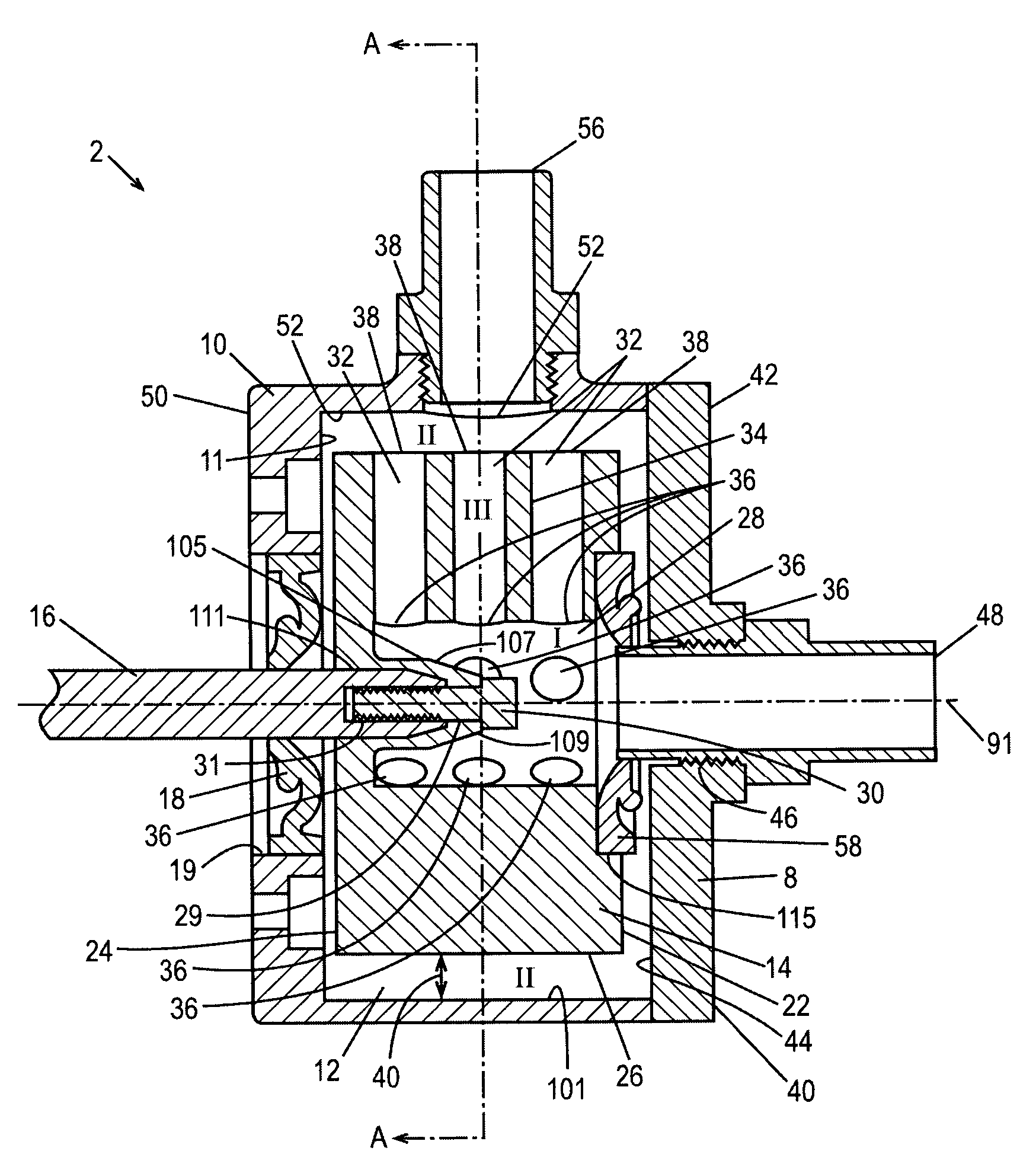
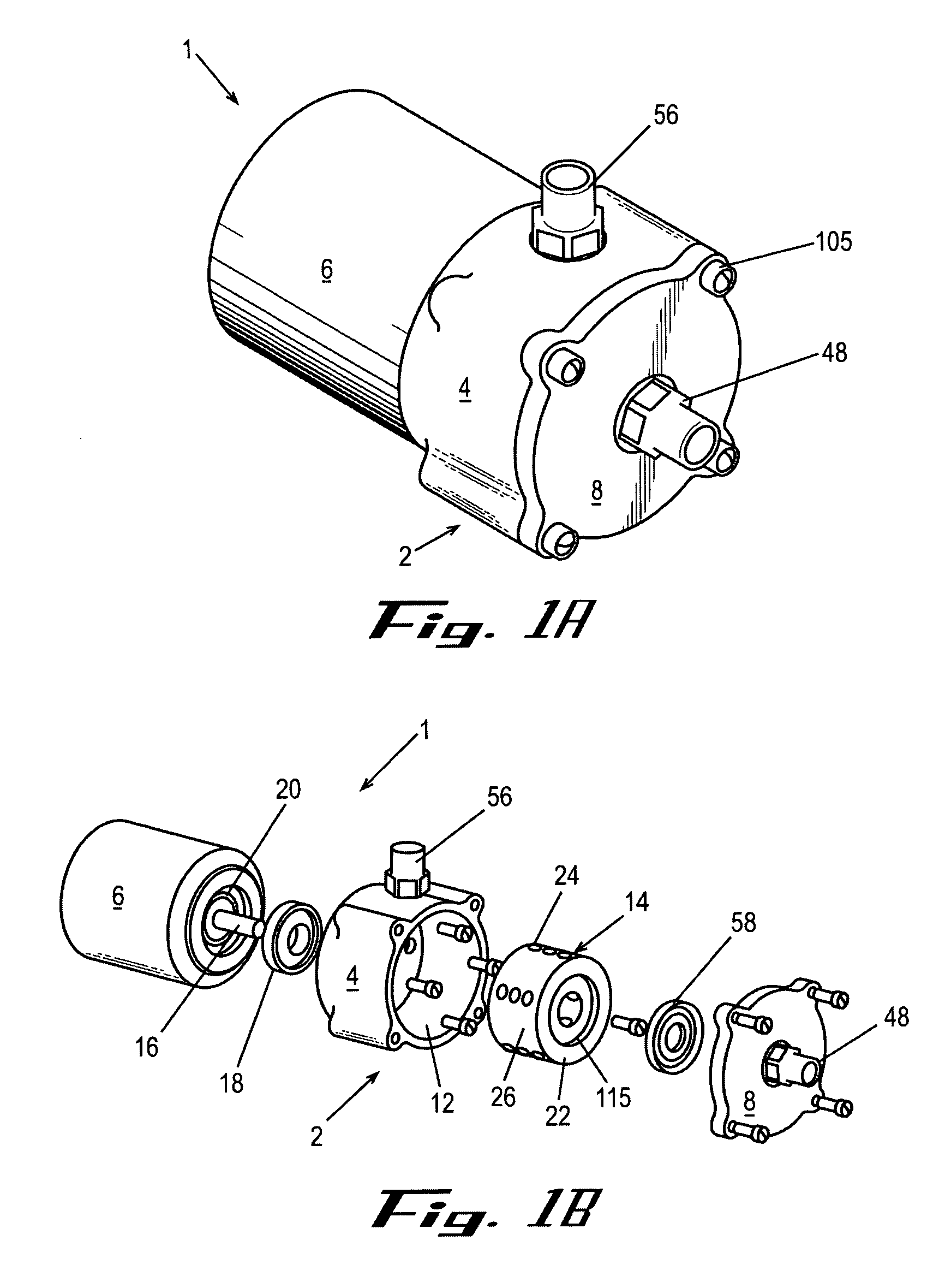
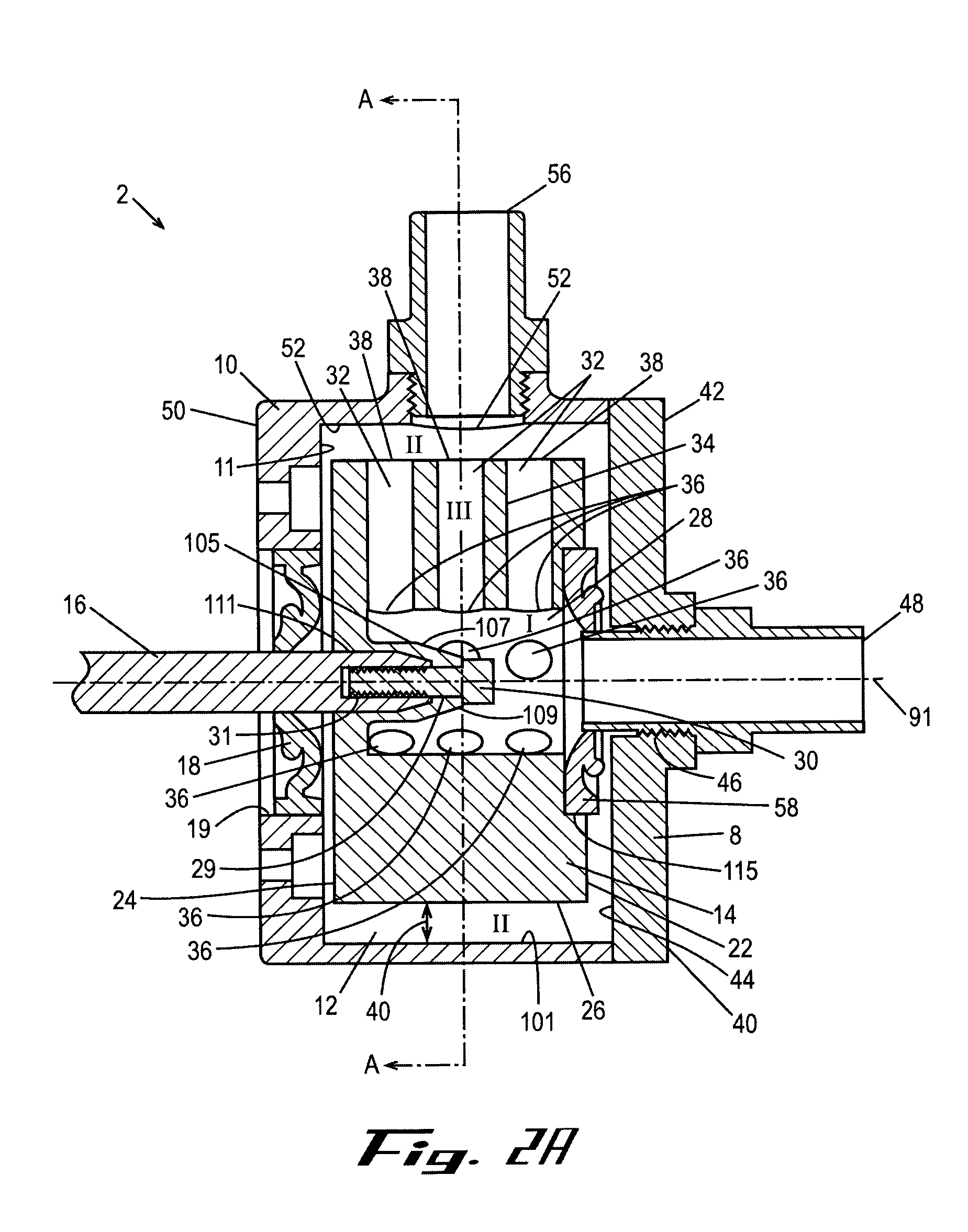
[0034]Many aspects of the preferred embodiments, among others, of the invention can be better understood with reference to the following drawings. The components in the drawings are not necessarily to scale, emphasis instead being placed upon clearly illustrating the principles of the present invention. Moreover, in the drawings, like reference numerals designate corresponding parts throughout the several views. Except for some embodiments in which like numbers denote elements having at least one structural or functional similarity.

[0035]For the purposes of this disclosure the following definitions are provided:

Vaporization: the formation of vapor bubbles within a fluid at a temperature lower in value than its normal boiling point for a given pressure.

Cavitation: the formation and subsequent collapse of vapor bubbles within a fluid at a temperature that is below its normal boiling point for a given pressure.

Centrifugal force: the component of apparent force on a element in curviline...


PUM


Abstract

An apparatus and method for generating cavitation in fluids is disclosed. The apparatus includes a housing for receiving a rotor, which is driven by a motive force. Multiple embodiments of the rotors are disclosed including, but not limited to, centrally feed, centrally drained, face feed, and face drained rotors. In one preferred embodiment, cavitation is enhanced by inducing tensile stress in the fluid by subjecting the fluid centrifugal force or centripital force depending upon the flow of the fluid.

Description

CROSS-REFERENCE TO RELATED APPLICATIONS[0001]The present application claims the benefit of the following U.S. Provisional Patent Applications: Ser. No. 60 / 414,238, filed Sep. 26, 2002; Ser. No. 60 / 419,751, filed Oct. 18, 2002; Ser. No. 60 / 428,073, filed Nov. 21, 2002; Ser. No. 60 / 441,623, filed Jan. 21, 2003; Ser. No. 60 / 463,689, filed Apr. 16, 2003; Ser. No. 60 / 448,017, filed Feb. 18, 2003; Ser. No. 60 / 453,139, filed Mar. 10, 2003; Ser. No. 60 / 478,881, filed Jun. 16, 2003; and Ser. No. 60 / 482,707, filed Jun. 26, 2003, all of which are hereby incorporated by reference.BACKGROUND OF THE INVENTION[0002]Hydrodynamic cavitation is a physical phenomenon that involves the formation and collapse of cavities within a liquid. The cavities (bubbles) are often filled with a vapor-gas mixture and are typically created by reducing a fluid's local pressure. The vapor bubbles, once formed, cannot hold their shape, being formed by fluid walls, and their rapid collapse creates mixing, emulsification...

Claims


Application Information

Patent Timeline
Patent Type & Authority Patents(United States)
IPC IPC(8): F01D1/34
CPCF01D1/34Y02E30/10
Inventor GARRETT, III, NORMAN H.
Owner GARRETT III NORMAN H
Why Eureka
Try Eureka