[0007]The foregoing problems are solved and a technical advance is achieved in an illustrative multiple ligating band delivery apparatus adapted for single hand operation to treat a hemorrhoid or other readily accessible
lesion under
direct observation, including using a anoscope. The present invention comprises a delivery member, typically an elongate, tubular member, that is configured for
insertion into a
body orifice, such as the
rectum. The
distal portion of the delivery member includes a tissue receiving chamber that is sized to accept a critical amount of tissue, such as a hemorrhoid, over which a ligating band is applied to cause
necrosis and eventual
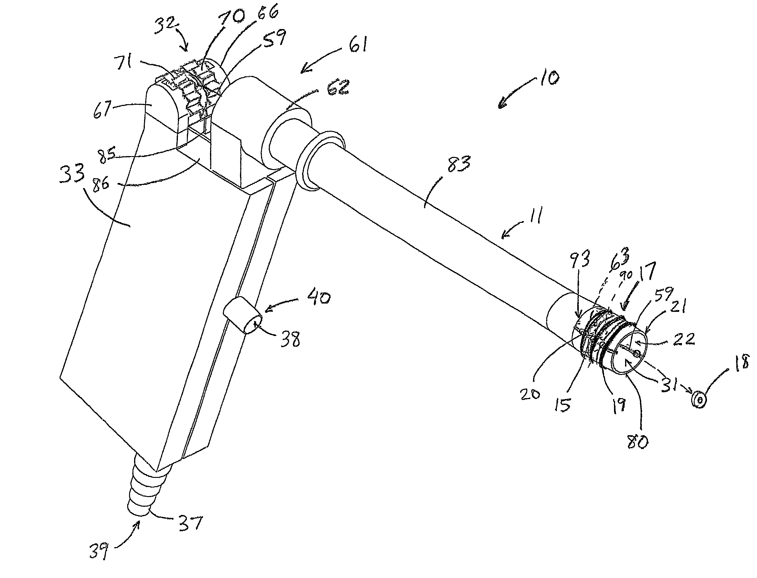
elimination of that tissue. The delivery member includes a passageway extending from the tissue receiving chamber to a suction means attachment port. When connected to a suction-creating device, tissue can be drawn into the receiving chamber where a ligating band is deployed over the distal edge of the delivery member (it should be noted that the term ‘distal end’ is synonymous with ‘distal edge’ in this application). The delivery member is configured such that a plurality of ligating bands can be placed thereover and then urged distally by one or more band carrier elements that are slidable relative to the delivery member. The band carrier elements, which can comprise either inner or outer members, such as strings, bands, teeth, slidable tubes, etc., are configured to carry or force the ligating bands over the distal edge of the delivery member in a sequential manner when the operator sequentially deploys the actuating mechanism. The actuating mechanism, which that part of an actuating
assembly directly manipulated by the operator, is located about the proximal portion of the apparatus, which is that portion of the apparatus that typically remains external to the patient. The actuating
assembly can include a variety of configurations, including those in which the proximal actuating mechanism is depressed, advanced, retracted, rotated, or otherwise moved by a portion of the operator's hand, while the suction is selectively sealed off via a suction actuating interface, which preferably comprises an external opening to the main suction passageway which extends from the tissue receiving chamber of the delivery member to the suction means attachment port at located about the proximal portion of the apparatus, which is attachable to a suction-generating means. When the suction actuating port is closed, such as by covering it with a
thumb or finger, or by a remote means, such as a foot pedal that operates a valve, it creates suction within the tissue receiving chamber which draws the tissue inward for banding. It is within the concept of this invention that the suction actuating interface be part of, operatively connected to the suction creating means such that the latter can be selectively activated and deactivated without the operator having to use the hand not used to manipulate the ligating band delivery apparatus (e.g., by using a foot pedal or some other means).
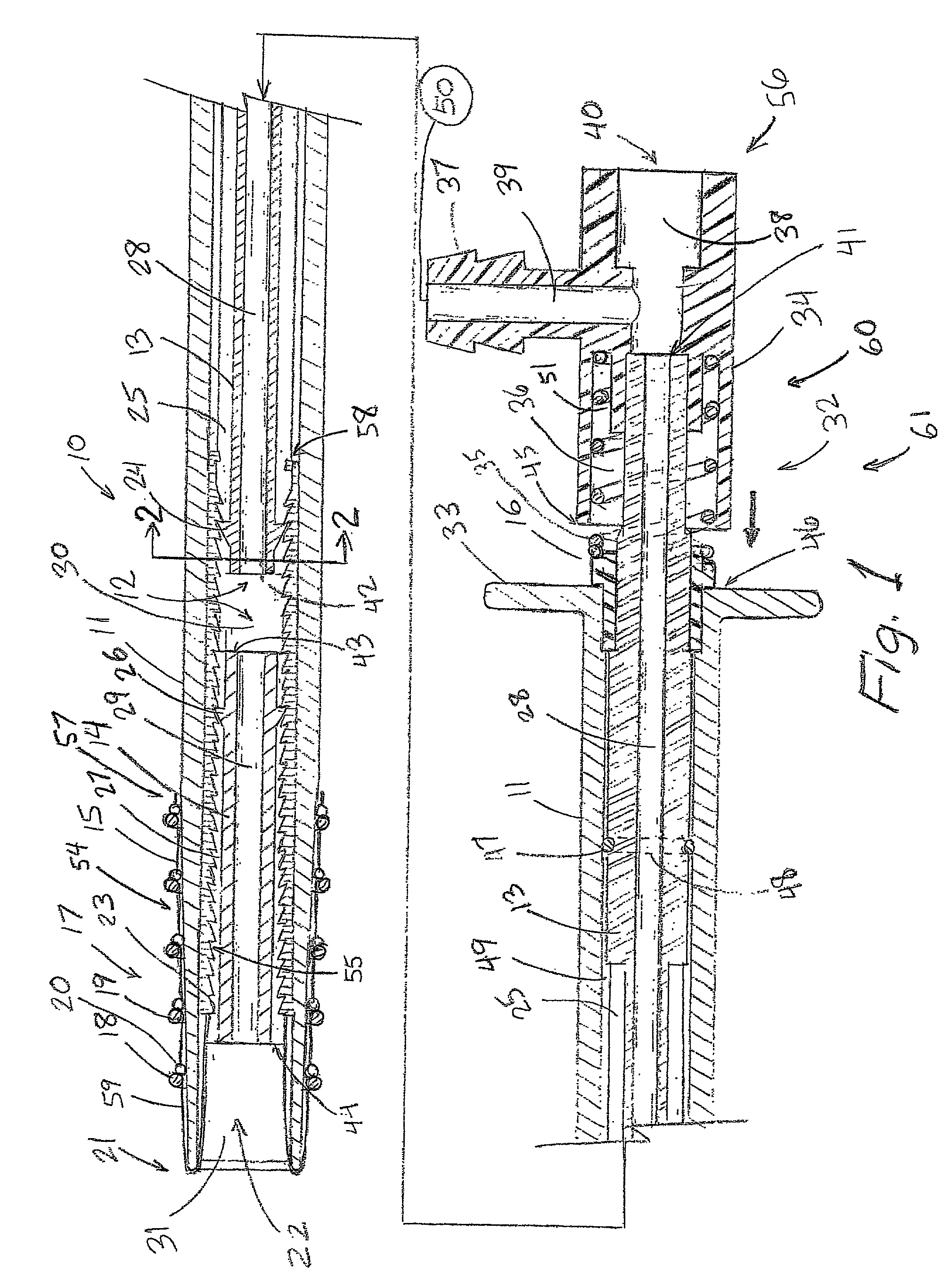
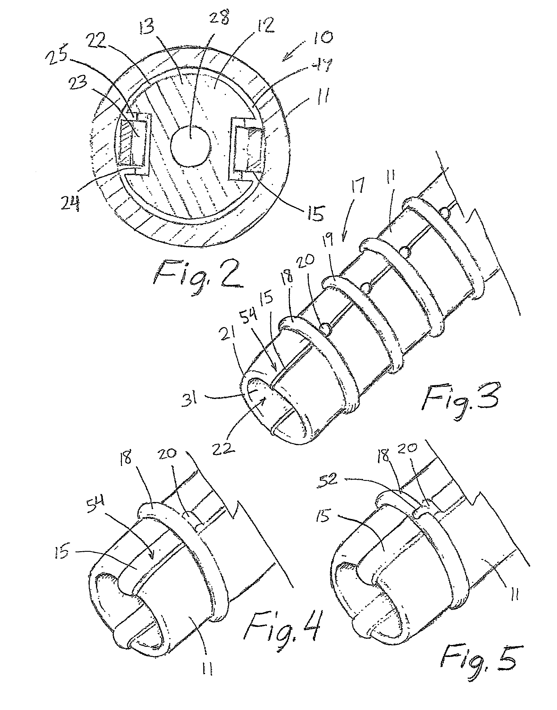
[0008]In a first illustrative embodiment of the present invention, the ligating band delivery apparatus comprises a tubular delivery member and an actuating mechanism comprising an inner member
assembly which includes a slidable engagement member. A plurality of standard ligating bands are preloaded over a pair of band-like band carrier elements, the first portion of each being slidably disposed over the outer surface of the delivery member. The first portion of the band carrier elements includes a plurality of retainers for holding the ligating bands at a selected position thereabout. The retainers are appropriately spaced to allow sequential delivery of the bands as the band carrier elements are advanced toward the distal end of the apparatus. The remaining second portion of each band carrier element is inverted into the passageway of the delivery member and each includes an engagement means, such as tooth-like
coupling members that cooperate with the engagement member of the inner member assembly to pull the band carrier elements into the delivery member passageway (this term is broadly defined to encompass any secondary passageways located therein), thereby advancing the ligating bands over the delivery member where they are deployed at the distal tip thereof. The actuating mechanism, which in the illustrative embodiment includes a spring and a
handle portion, is advantageously designed such that the band carrier elements are engaged after forward advancement of the actuating mechanism, but not deployed until the advancement mechanism is released. With regard to actuating mechanisms that operate to directly ‘push’ or urge the band off of the apparatus, the forward-directed force required to do so can be transferred from the actuating mechanism to the tip of the apparatus. This may compromise smooth and accurate delivery of the band in some instances. In the present invention, the forward advancement of the engagement member to engage the band carrier element can be perfomed prior to exact placement of the apparatus at the
target site. The apparatus can then be placed over the
target tissue that has been drawn into the receiving chamber, and each band is quickly and smoothly dislodged from the distal tip portion as the actuating mechanism is released. The design permits numerous bands be loaded over the delivery member without requiring it to be markedly tapered or stepped down in
diameter to facilitate the bands being pushed off the distal tip. This allows for the
distal portion of the passageway to receive a maximal amount of tissue if necessary while the delivery member is able to advantageously maintain a minimal outer
diameter because the lack of external pusher mechanism.

