
Anti-glare rearview mirror assembly and reflectance control method of same

Inactive Publication Date: 2005-12-13
EXON SCIENCE INC
View PDF12 Cites 9 Cited by
  • Summary
  • Abstract
  • Description
  • Claims
  • Application Information

AI Technical Summary

Benefits of technology

[0009]Therefore, an object of the present invention is to provide an anti-glare rearview mirror assembly capable of minimizing unnecessary color-change cycles and having a wide detection range.

Problems solved by technology

Glare is one of the troublesome factors when driving a vehicle.
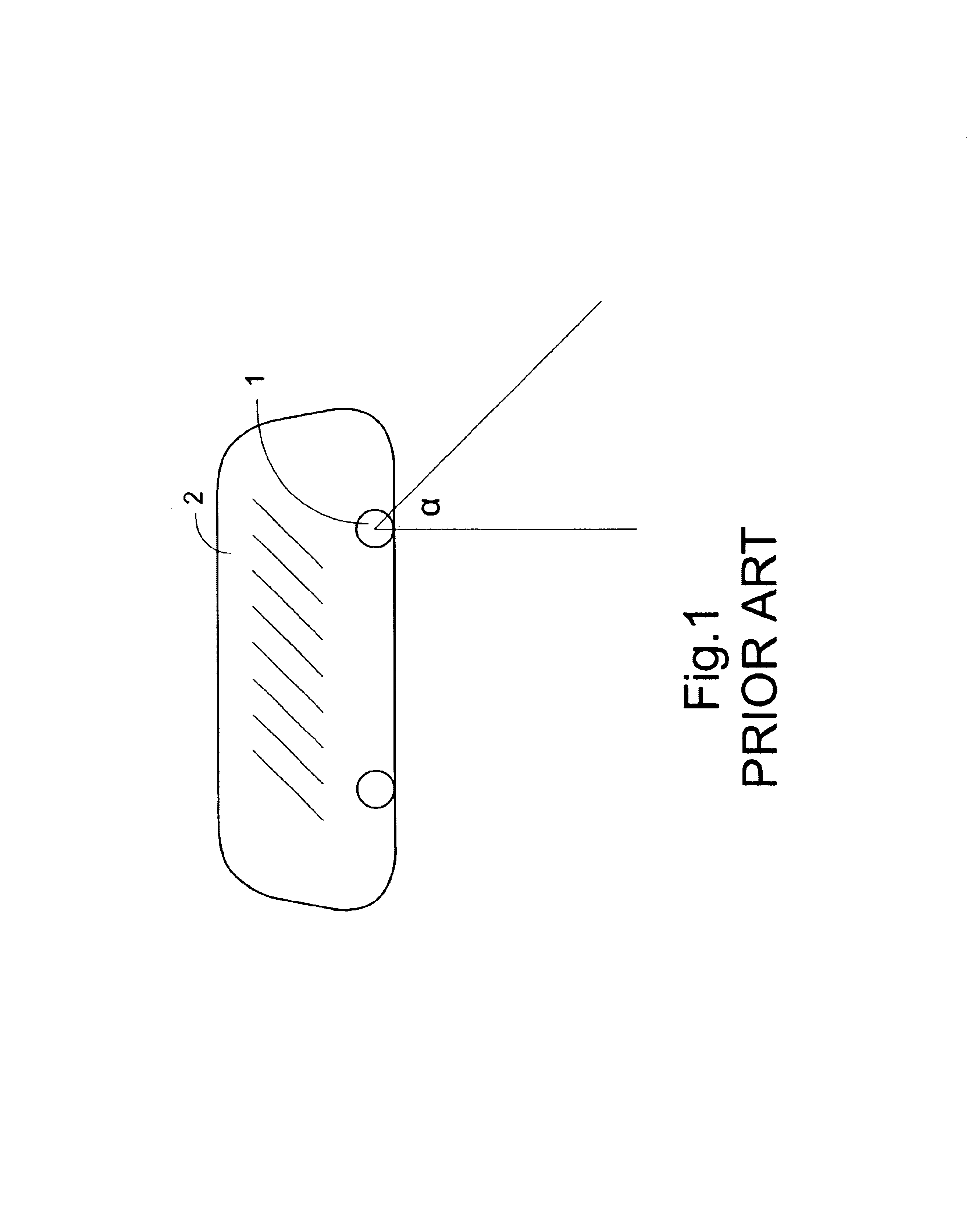
Furthermore, since the photo-detector 1 is oriented to a certain direction and has a confined detection range α, the glare situation beyond the detection range α cannot be detected and solved.
This conventional anti-glare mechanism, in spite of saving unnecessary operation cycles of the electrochromic units, may still waste many cycles under sufficient ambient illumination in the nighttime.
Moreover, since the above-mentioned electrochromic mechanism does not work in daytime, the glaring effect resulting from intense sunrise or sunset sunlight cannot be avoided.
This conventional electrochromic rearview mirror system, in spite of further reducing unnecessary operation cycles of the electrochromic units, still has the problem of the narrow detection range.

Method used


Image

  • Anti-glare rearview mirror assembly and reflectance control method of same
  • Anti-glare rearview mirror assembly and reflectance control method of same
  • Anti-glare rearview mirror assembly and reflectance control method of same

Examples


Embodiment Construction

[0044]The present invention will now be described more specifically witch reference to the following embodiments. It is to be noted that the following descriptions of preferred embodiments of this invention are presented herein for purpose of illustration and description only; it is not intended to be exhaustive or to be limited to the precise form disclosed.

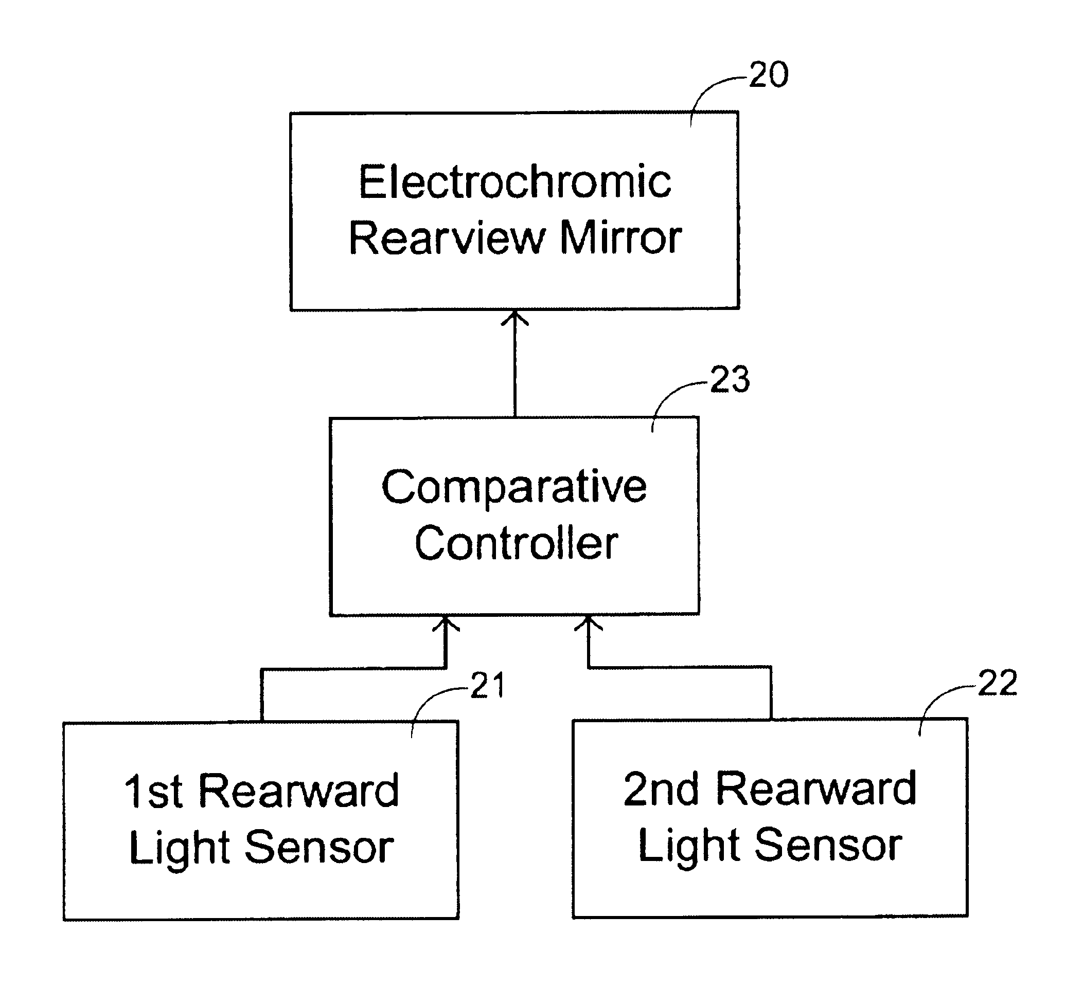
[0045]Please refer to FIGS. 3A and 3B, which illustrate an anti-glare rearview mirror assembly according to the present invention. The anti-glare rearview mirror assembly includes an electrochromic mirror 20, a first rearward light sensor 21, a second rearward light sensor 22 and a comparative controller 23. The rearward light sensors 21 and 22 are disposed on the same side of the mirror 20, but oriented different directions so as to have detecting ranges β and γ, respectively. It is apparent that the detection ranges are enlarged, compared to the prior art. For example, as shown in FIG. 3A, the two sensors 21 and 22 are arrange...


PUM


Abstract

An anti-glare rearview mirror assembly and a reflectance control method thereof are disclosed. The assembly includes an electrochromic rearview mirrors, two rearward light sensors, and a comparative controller. The sensors receiving a first rearward light from a first specified region and a second rearward light from a second specified region at the same time point, respectively, wherein the first and second specified regions partially overlap with each other. The intensities of the first and second rearview mirror light are compared to obtain a light difference. The reflectance of the anti-glare rearview mirror is adjusted according to the light difference.

Description

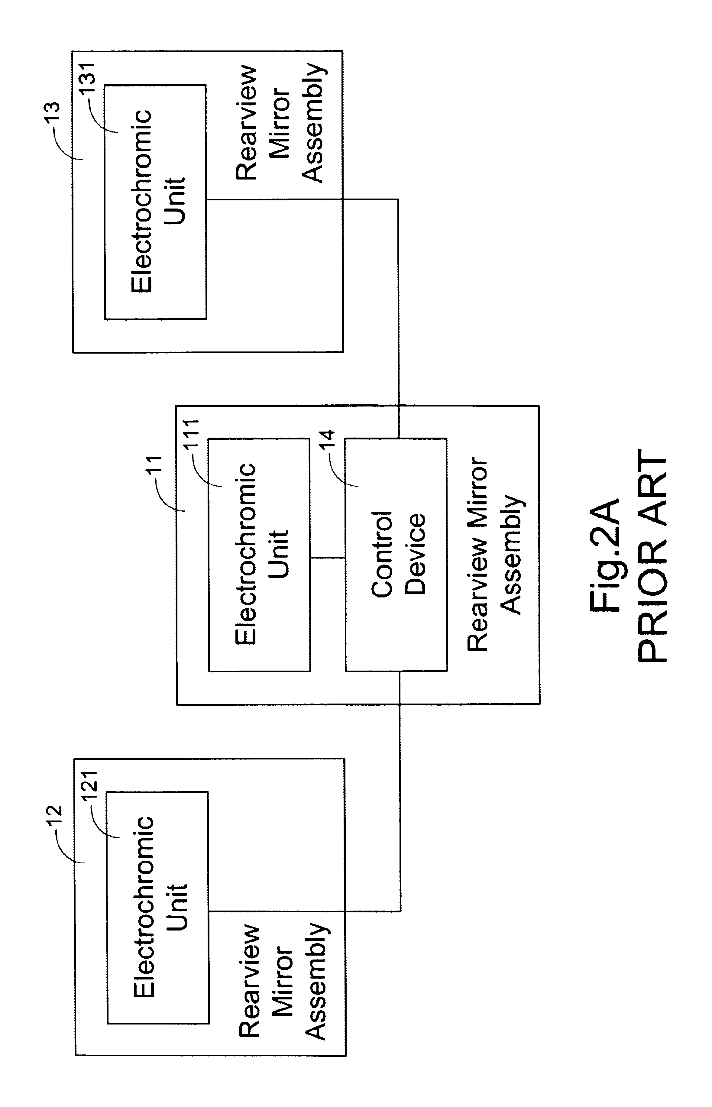
FIELD OF THE INVENTION[0001]The present invention relates to an anti-glare rearview mirror assembly, and more particular to an anti-glare rearview mirror assembly with a wide glare-detection range. The present invention also relates to a reflectance control method of an anti-glare rearview mirror assembly.BACKGROUND OF THE INVENTION[0002]Glare is one of the troublesome factors when driving a vehicle. Many efforts have been made to solve the glaring problem. One of the most effective ways is to provide an electrochromic unit for the rearview mirror of the vehicle. The electrochromic unit deepens the color and thus reduces the reflectance of the mirror according to the degree of the glare, thereby minimizing the glaring effect.[0003]FIG. 1 is a schematic diagram showing a conventional anti-glare rearview mirror. A photo-detector 1 is mounted on an electrochromic rearview mirror 2, and oriented to detect rearward light. The photo-detector 1 outputs a control signal to the electrochromi...

Claims


Application Information

Patent Timeline
IPC IPC(8): G02F1/15B60R1/04B60R1/06B60R1/08G01J1/26
CPCG01J1/26B60R1/088
Inventor SU, WEN-WEICHEN, KUEI-HUNGHSIAO, SHUN-HSIANG
Owner EXON SCIENCE INC
Learn More