Method and apparatus for calibrating piezoelectric driver in dual actuator disk drive

Inactive Publication Date: 2005-12-13
MAXTOR
View PDF1 Cites 119 Cited by
  • Summary
  • Abstract
  • Description
  • Claims
  • Application Information

AI Technical Summary

Benefits of technology

[0018]The capacitance measurement may be conducted following the manufacture of the disk drive. In this manner, after a disk drive is in operation, variation in th

Problems solved by technology

As a result, maintaining the transducer or head in an accurate track following position for purposes of reading and writing is becoming more complex.
Unfortunately, a charge control driver has several disadvantages.
One such disadvantage is that a charge control driver requires relatively complex circuitry in order to be able to drive a specific amount of charge into and out of the piezoelectric device, as compared to the circuitry required for a voltage control driver.
This relatively complex circuitry is also expensive to design and manufacture, as compared to a voltage control driver.
Another disadvantage of a charge control driver is that the

Method used


Image

  • Method and apparatus for calibrating piezoelectric driver in dual actuator disk drive
  • Method and apparatus for calibrating piezoelectric driver in dual actuator disk drive
  • Method and apparatus for calibrating piezoelectric driver in dual actuator disk drive

Examples


Embodiment Construction

[0026]While this invention is susceptible of embodiments in many different forms, there are shown in the drawings and will herein be described in detail, preferred embodiments of the invention with the understanding that the present disclosure is to be considered as an exemplification of the principles of the invention and is not intended to limit the broad aspects of the invention to the embodiments illustrated.

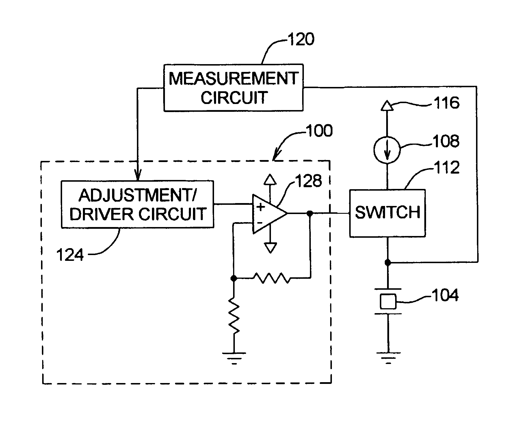
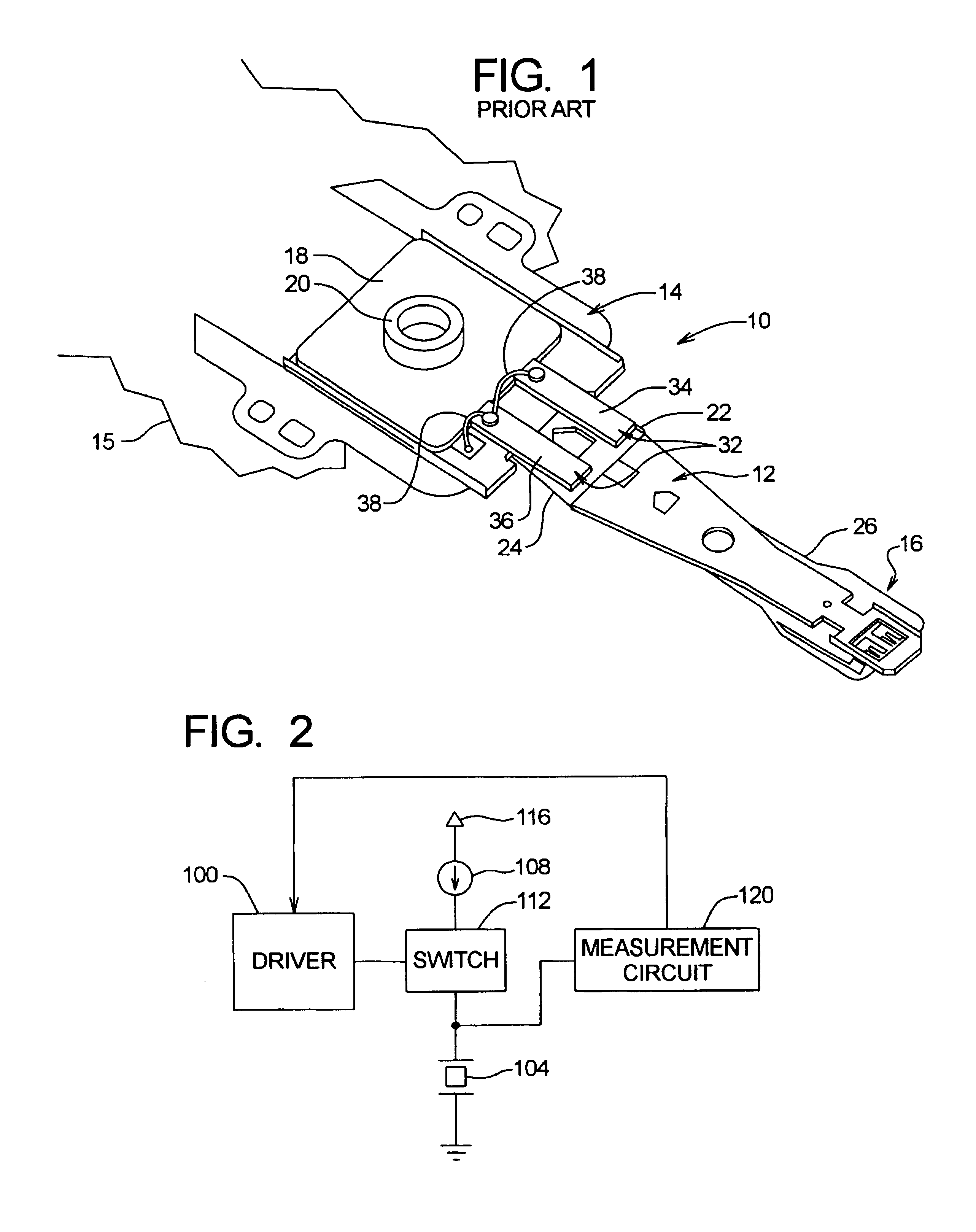
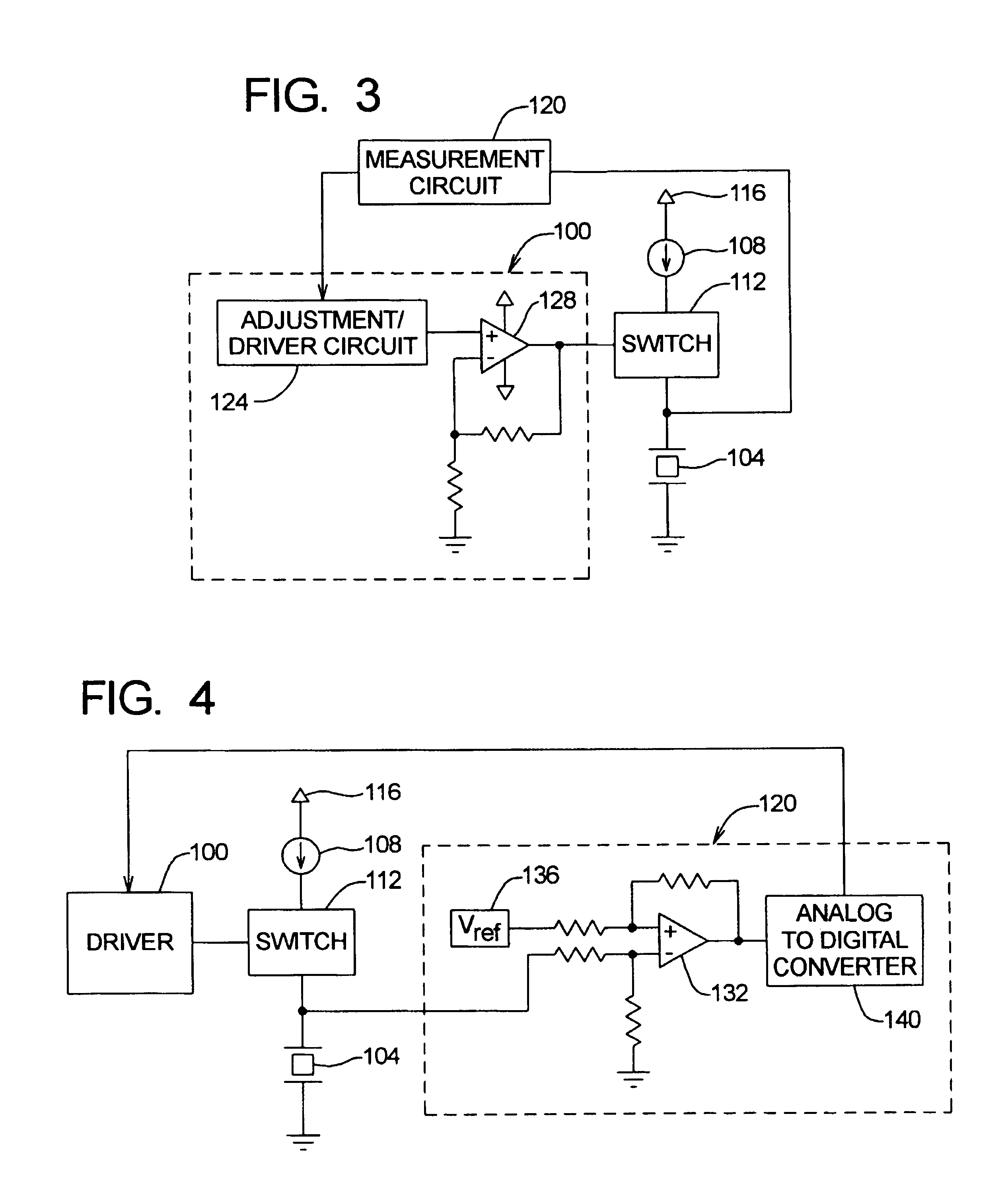
[0027]Referring to FIG. 2, a block diagram illustration of a driver, calibration, and measurement circuit for a dual actuator disk drive is now described. The circuit includes a driver 100 which drives a piezoelectric actuator 104. The circuit also includes a calibration supply 108, and a mode switch 112, which switches the piezoelectric actuator 104 between the driver 100 and the calibration supply 108.

[0028]The calibration supply 108 is connected to a voltage source 116, and is operable to supply a constant current (Ical) into the piezoelectric actuator 104, which is used ...


PUM


Abstract

A method and apparatus are disclosed which are operable to determine a capacitance associated with at least one piezoelectric element in an dual actuator disk drive. The capacitance information is used to adjust a driver used to drive the piezoelectric element. Capacitance is determined by supplying a predetermined current into the piezoelectric element(s) for a predetermined time period. A voltage associated with the piezoelectric element(s) is measured following the predetermined time period. The capacitance of the piezoelectric element(s) is then calculated based on the measured voltage, the current supplied, and the predetermined time period.

Description

[0001]Priority is claimed from U.S. Provisional Patent Application No. 60 / 257,005, filed Dec. 20, 2000 entitled “Piezo Driver With Constant Current Calibration Mode,” which is incorporated by reference in its entirety.FIELD OF THE INVENTION[0002]The invention relates generally to digital data storage systems and, more particularly, calibration of piezoelectric drivers in dual actuator hard disk drives.BACKGROUND OF THE INVENTION[0003]A hard disk drive typically includes one or more magnetic disks rotatably mounted in association with a spindle and one or more actuators for positioning a transducer or head relative to data tracks on the surface of each disk. The actuator typically comprises a pivotable base plate, a load beam or suspension arm affixed to the base plate, a flexure at the distal end of the load beam and a slider and transducer or a head assembly affixed to the flexure. A voice coil motor induces movement of the actuator to position the head relative to the disk surface...

Claims


Application Information

Patent Timeline
IPC IPC(8): G01R33/12G11B5/55G11B5/596G11B21/24
CPCG11B5/5552G11B5/59627
Inventor MALANG, KEITHHUTSELL, LARRY
Owner MAXTOR
Why Eureka
Try Eureka