Thin film magnetic recording inductive write head with laminated write gap

a write gap and write head technology, applied in the field of thin film magnetic recording inductive write head for magnetic recording, can solve the problem of reducing the density of tracks that can be achieved on the disk

Inactive Publication Date: 2005-12-13
IBM CORP
View PDF26 Cites 2 Cited by
  • Summary
  • Abstract
  • Description
  • Claims
  • Application Information

AI Technical Summary

Benefits of technology

[0008]The invention is a thin film inductive write head with a write gap formed as a lamination of alternating layers of a nonmagnetic gap layer and a ferromagnetic spacer layer. There are N gap layers and N−1 spacer layers, with each pole tip of the write head being located adjacent to a gap layer. The spacer layers in the gap structure are formed of a ferromagnetic material with a high saturation moment density (BS) that is close to the BS of the spacer material from which the pole

Problems solved by technology

However, a larger write gap also results in a wider write bubble in the off-track direction to

Method used


Image

  • Thin film magnetic recording inductive write head with laminated write gap
  • Thin film magnetic recording inductive write head with laminated write gap
  • Thin film magnetic recording inductive write head with laminated write gap

Examples


Embodiment Construction

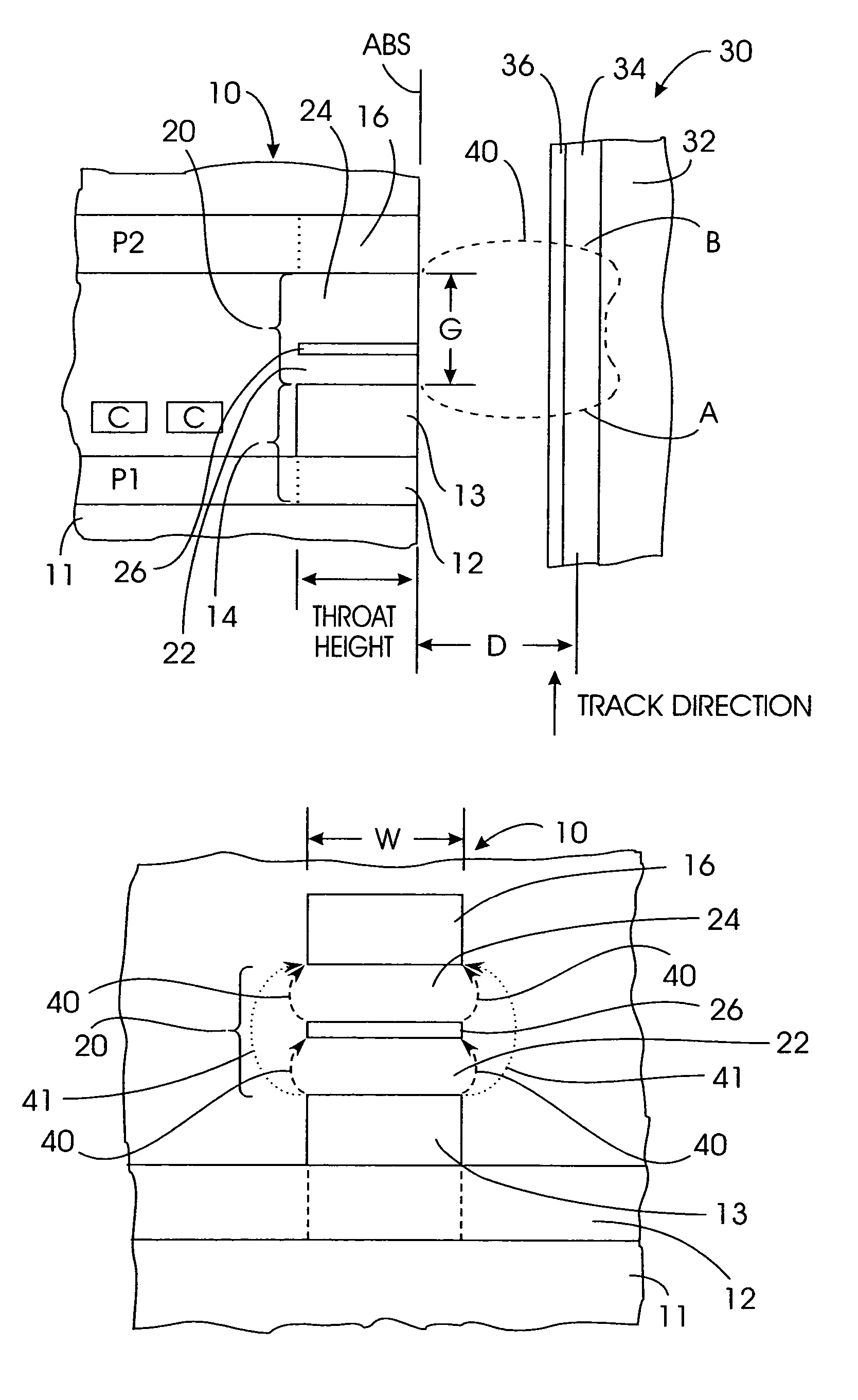
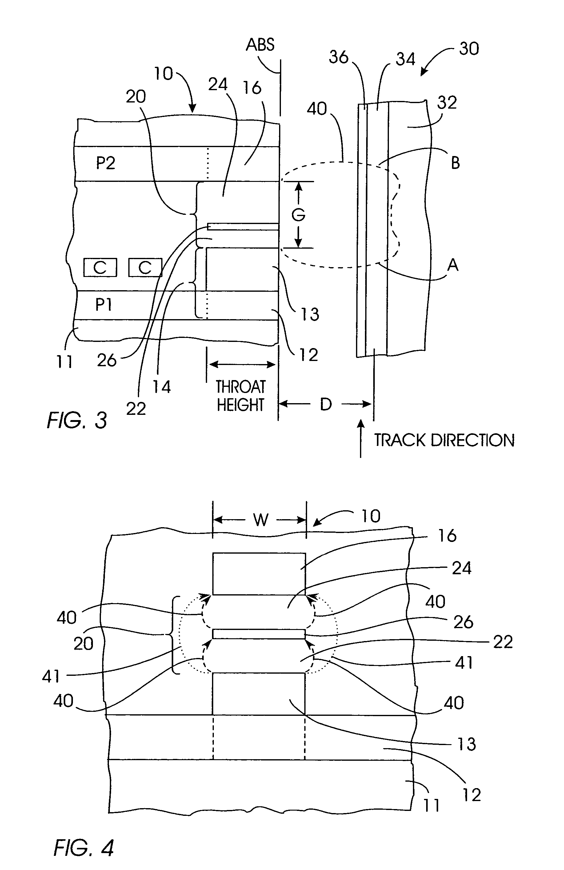
[0015]The present invention is shown in the side sectional view of FIG. 3, where the thin film inductive write head 10 is shown with its air-bearing surface (ABS) facing a magnetic recording disk 30. FIG. 4 is a view of the head 10 as it would be seen from the disk with the ABS being in the plane of the paper. The head 10 is a series of layers formed on a substrate 11, which is typically the trailing surface of an air-bearing slider. The head has a lower or first pole P1 formed of ferromagnetic material with a pole tip 14 that includes a bottom pole tip portion 12 and a “pedestal” pole tip portion 13 on top of bottom pole tip portion 12. The head has an upper or second pole P2 formed of ferromagnetic material that includes a portion that serves as a pole tip 16. Portions of the electrically conductive coil C are shown between poles P1 and P2. The pole tips 14, 16 have a “throat height” defined by the “height” of the pedestal pole tip portion 13.

[0016]The disk 30 includes a substrate...


PUM


Abstract

A thin film inductive write head for magnetic recording has a write gap formed as a lamination of alternating layers of a nonmagnetic gap layer and a ferromagnetic spacer layer. There are N gap layers and N−1 spacer layers, with each pole tip of the write head being located adjacent to a gap layer. The spacer layers in the gap structure are formed of a ferromagnetic material with a high saturation moment density (BS) that is close to the BS of the spacer material from which the pole tips are formed. Unlike the pole tips, the spacer layers are not part of a magnetic circuit and are magnetically isolated, i.e., completely surrounded by nonmagnetic gap material. The effect of the spacer layers is to effectively divide the gap into a plurality of smaller gaps. The write head with the laminated gap creates a write bubble that is narrower in the off-track direction and wider in the in-track direction.

Description

[0001]This application is a continuation of U.S. application Ser. No. 10 / 147,565 titled “THIN FILM MAGNETIC RECORDING INDUCTIVE WRITE HEAD WITH LAMINATED WRITE GAP”, filed May 15, 2002 (which issued as U.S. Pat. No. 6,833,976), the disclosure of which is hereby incorporated by reference in its entirety.TECHNICAL FIELD[0002]This invention relates generally to a thin film inductive write head for magnetic recording, and more particularly to a thin film write head having an improved write gap.BACKGROUND OF THE INVENTION[0003]In a magnetic recording disk drive, data is written by thin film magnetic transducers called “write heads” that are supported over the surface of the disk while the disk is rotated at high speed. Each write head is located on the trailing surface of a slider that is supported by a thin cushion of air (an “air bearing”) produced by the disk's high rotational speed.[0004]A prior art thin film inductive write head is shown in the side sectional view of FIG. 1 and the ...

Claims


Application Information

Patent Timeline
IPC IPC(8): G11B5/00G11B5/09G11B5/187G11B5/23G11B5/31G11B5/39G11B5/48
CPCG11B5/3116G11B5/313G11B5/3143G11B5/09G11B5/187G11B5/23G11B5/3146G11B5/3967G11B5/488G11B2005/001G11B2005/0013G11B2005/0026
Inventor HSU, YIMINTSANG, CHING HWA
Owner IBM CORP
Why Eureka
Try Eureka