
Method of repairing damaged concrete slabs

Active Publication Date: 2005-12-20
ASPLIN CHARLES LEE
View PDF29 Cites 47 Cited by
  • Summary
  • Abstract
  • Description
  • Claims
  • Application Information

AI Technical Summary

Benefits of technology

[0009]It is an further objective of the present invention to provide such a method of repairing concrete slabs which is highly portable and capable of operating independently from all external power sources and which is economical and efficient in its operation.
[0011]These objectives are accomplished by the use of a concrete slab leveling system that employs lime sludge as a fill material which is a mixture of calcium, magnesium, and water that is a common byproduct of water softening processes. Additionally, the chemical makeup of the lime sludge is similar to that of mortar and cement and provides similar structural integrity properties when dried. The use of the lime sludge imparts these cement-like qualities to the fill when dried while retaining the fluid qualities when fully hydrated that allows for its easy pumping through hoses and other components used in these operations. Additionally, the use of the lime sludge improves the lift characteristics of the fill material due to its viscous nature allowing a concrete slab to be easily lifted even when there is little or no settle cavity between the concrete slab and the underlying ground.
[0015]The expansion of the operational cylinders draws the fill material from their interiors from the pump manifold which ties the pump assembly to the material bin. The pump manifold is equipped with two one-way valves which control the flow of the fill material within the pump assembly. The first of these valves, the forward one-way valve, lies between the interior of the bin and the pump manifold and functions to allow the flow of fill material into the manifold as the cylinders are expanded. Conversely in this operation the rearward one-way valve lies between the pump manifold and its outlet the manifold pipe and functions to keep fill in the manifold pipe from being drawn back into the pump manifold.
[0016]Once the expansion of the hydraulic cylinder is complete and the operational cylinders are full, the hydraulic cylinder is then contracted which forces the fill within the operational cylinders back into the pump manifold. This reversal of flow closes the forward one-way valve thereby blocking the flow of the fill back into the bin and opens the rearward one-way valve allowing the fill to be forced into the manifold pipe and to a delivery mechanism to be forced under a settled section of concrete slab. Additionally, the use of the pump assembly in conjunction with the fill material provides enough pressure at the point of delivery to elevate even the largest concrete slab in common use today.
[0018]Once the concrete slab has been lifted by the process described above, the nature of the lime sludge leaves some open space in the settle cavity between the lower surface of the concrete slab and the surface of the ground. This is a result of the viscous nature of the fill material as it does not need to fill the entire settle cavity before lifting the slab. This characteristic of the material fill allows the user to pack the remaining open space with dried mason's sand which, because of its stable nature, further solidifies the repair. The sand fill is accomplished by drilling more holes into the slab and injecting the sand into the openings. Once these processes have been completed, the open holes in the concrete slab are filled in with an appropriate material to complete the repair of the concrete slab.

Problems solved by technology

Regardless of the care and skill used in the initial construction, concrete slabs tend to become misaligned over time due to different rates of settlement of the earth.
Uplift from freeze / thaw cycles or tree root lifting are also common causes of slab misalignment.
These problems cause cracks in the cement slab to develop and can also cause step-like structures to occur between sections of the slab.
The end result of this condition is the creation of hazards to its users and liability for those who are responsible for their care.
Additionally, the uneven cement slabs are extremely difficult to clear of snow and ice during the winter months in the northern areas of the United States, thus creating further hazards and liabilities for their users and owners.
The problem with this method is that although it works very well, it is time consuming and very expensive.
The problem with this method is that it still leaves uneven slab surfaces that are hazardous and difficult to maintain.
The first problem with this method is that the mud commonly used in this process is not viscous enough to provide an adequate amount of force to the cement slab to lift it enough to effectuate the repair.
Another problem with the mud jacking method is that it requires that there be a substantial open area, or settle cavity, between the lower surface of the concrete slab on the underlying ground.
Finally, the use of wet mud makes for an ineffectual repair as it tends to settle over time while drying resulting in a cement slab surface that retains the uneven condition that was intended to be repaired.
The problem with this device is that by nature of its construction, a heavy frame supported by four wheels, it is large and cumbersome in operation.
Further, this device requires the even lifting of a given slab in only small sections at a time, as one portion of the device rests on an un-lifted portion of the sidewalk.
However, the resulting apparatus is still large and cumbersome in its operation.
Additionally, these solutions are not capable of raising large sections of cement slabs and are therefore limited in their applications.

Method used


Image

  • Method of repairing damaged concrete slabs
  • Method of repairing damaged concrete slabs
  • Method of repairing damaged concrete slabs

Examples


Embodiment Construction

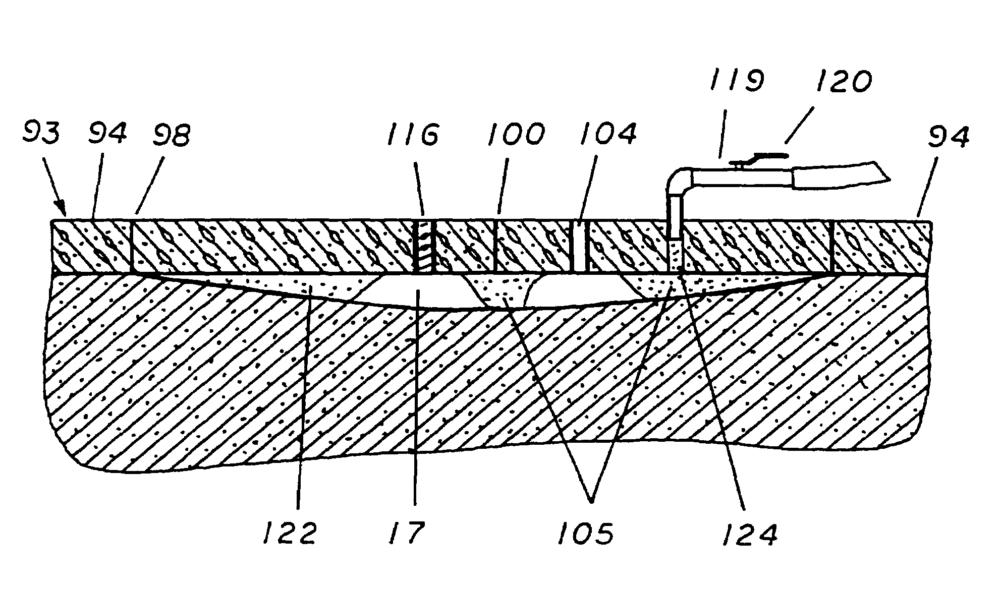
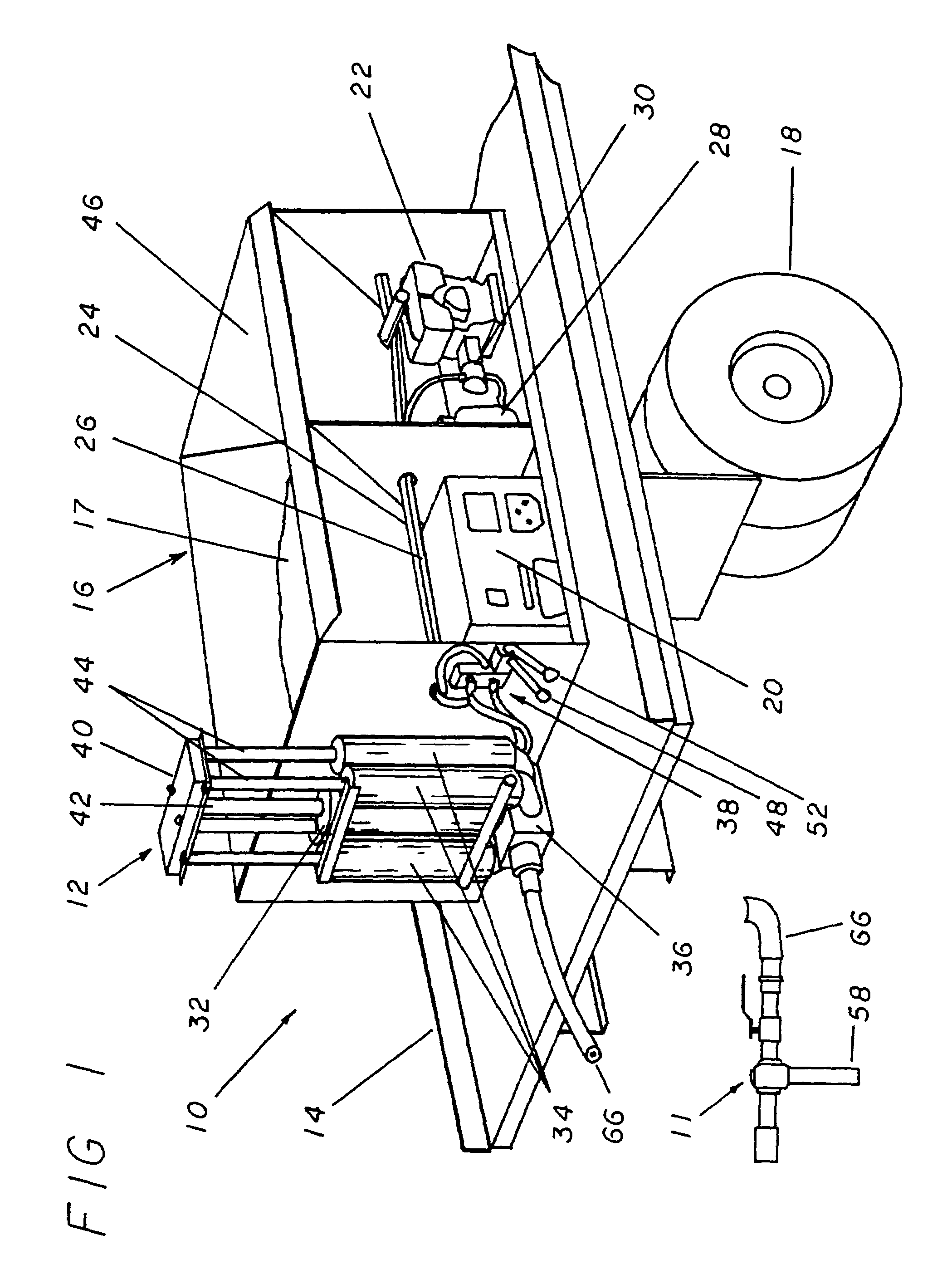
[0029]Referring now to the drawings, and more specifically to FIG. 1, the present invention is employed to repair concrete slabs by making use of a plurality of devices to introduce lime sludge 17 in the desired location. The first of these is a slab lift pump apparatus 10 which is a self contained portable device that is employed to pump at pressure the lime sludge 17 through the connected tool hose 66. The portable aspect of the slab lift pump apparatus 10 is accomplished by placing its components on a flatbed 14 vehicle that is equipped with a set of wheels 18 such as a truck or trailer. Additionally, all of the components of the slab lift pump apparatus 10 that are necessary for its operation are contained on the surface of the flatbed 14 which allows it to be quickly moved from site to site and to operate completely independently.

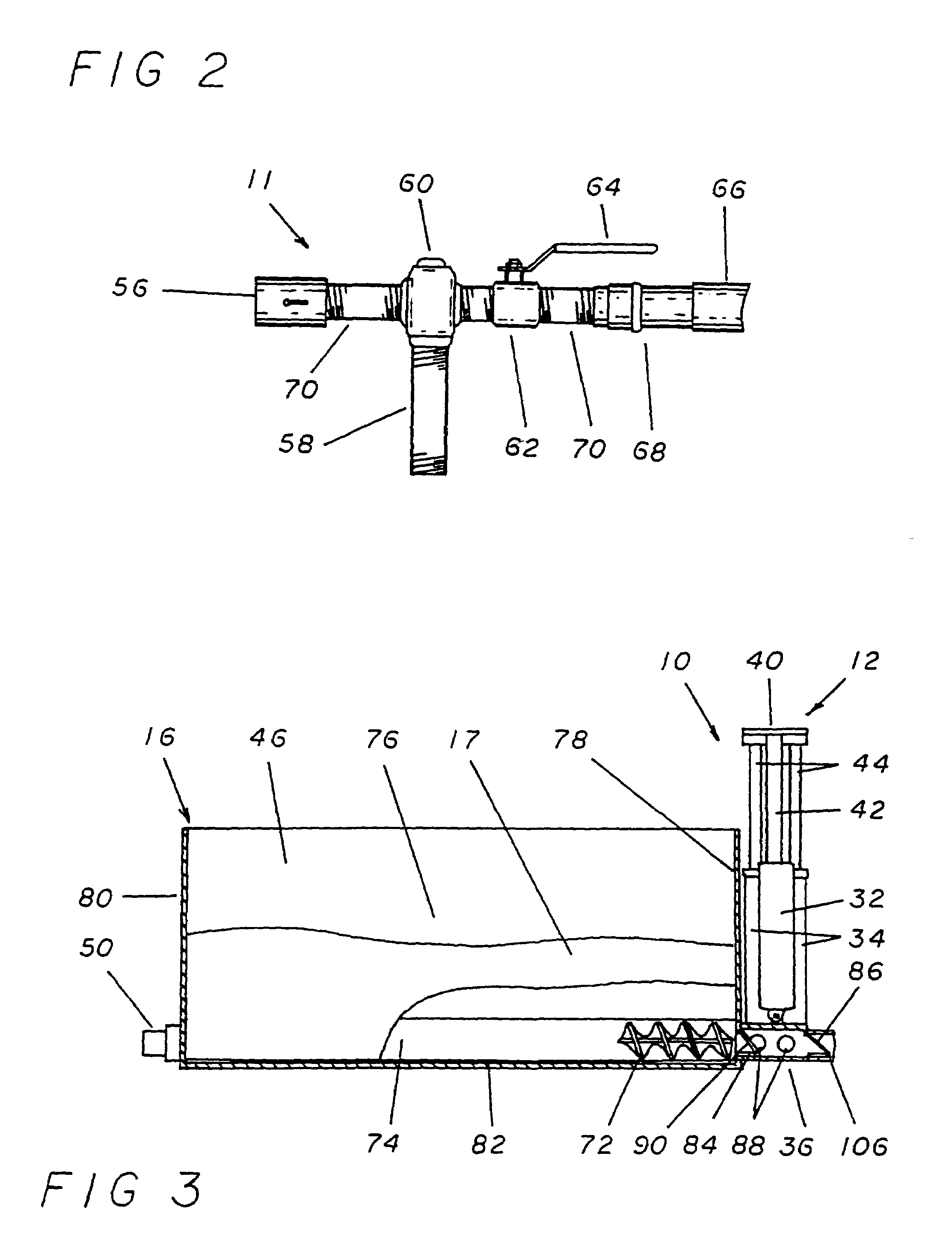
[0030]The slab lift pump apparatus 10 is made up of a large open topped fill container 16 within which the lime sludge 17 that is used to elevate the ...


PUM


Abstract

A method of repairing concrete slabs that have become uneven and dangerous is provided that employs lime sludge that is injected under pressure into the space between the lower surface of the damaged concrete slab and the underlying ground to raise that slab back into a level orientation. Once this has been accomplished, any remaining space below the slab is filled in with well dried sand blown in under pressure.

Description

BACKGROUND OF THE INVENTION[0001]The present invention relates to a method of repairing an existing section of concrete slab which has had portions settle into the ground so as to become uneven over time. More specifically, to a method of carefully raising a section of settled cement slab so as not to damage the section and allow for the injection of pressurized mason's sand into the cavity created between the bottom of the uneven cement slab and the settled ground.[0002]Regardless of the care and skill used in the initial construction, concrete slabs tend to become misaligned over time due to different rates of settlement of the earth. Uplift from freeze / thaw cycles or tree root lifting are also common causes of slab misalignment. These problems cause cracks in the cement slab to develop and can also cause step-like structures to occur between sections of the slab. The end result of this condition is the creation of hazards to its users and liability for those who are responsible f...

Claims


Application Information

Patent Timeline
IPC IPC(8): E01C23/10
CPCE01C23/10
Inventor ASPLIN, CHARLES LEE
Owner ASPLIN CHARLES LEE
Learn More