Minimally invasive retinal prosthesis

Inactive Publication Date: 2005-12-20
MASSACHUSETTS EYE & EAR INFARY +1
View PDF83 Cites 156 Cited by
  • Summary
  • Abstract
  • Description
  • Claims
  • Application Information

AI Technical Summary

Benefits of technology

[0019]The present invention discloses an ocular device that can more safely and effectively perform all functions needed of a retinal prosthesis with electronic components that are placed outside the wall of an eye, are powered wirelessly provided by an external power source, and which provide a patient with a view determined by natural motion of the eye and triggered by natural incident light converging at the retina. In one aspect, the invention is an externally powered, light-activated, sub-retinal prosthesis in which natural light entering the eye conveys visual details to the s

Problems solved by technology

Age-related macular degeneration results in a loss of central vision, which eliminates a person's ability to read or recognize faces.
Although devices in either location are capable of effectively stimulating retinal nerve cells, there are advantages and potential disadvantages to each strategy.
An additional disadvantage is that, in simple implementations, the view the patient sees is determined artificially by motion of the external camera rather than by the natural motion of the eye.
The goal of creating “useful” vision is extremely challenging, primarily because of the intricacy of human vision, the complexity of the nerve circuitry that provides vision, and because of the potential for the body to reject implantation of a foreign object, especially near the retina, which is as delicate and complex as the rest of the brain.
Driving the larger number of electrodes needed for this purpose imposes greater demands upon the power delivery of the prosthesis, which must in turn obtain that power from an artificial, external source, given that the intensity of the incident light that illuminates the retina is woefully insufficient to electrically activate nerve cells (which evolved to respond with high sensitivity to light, not electricity)).
The relatively intense power source required has the potential to damage the retina because of the un

Method used


Image

  • Minimally invasive retinal prosthesis
  • Minimally invasive retinal prosthesis
  • Minimally invasive retinal prosthesis

Examples


Embodiment Construction

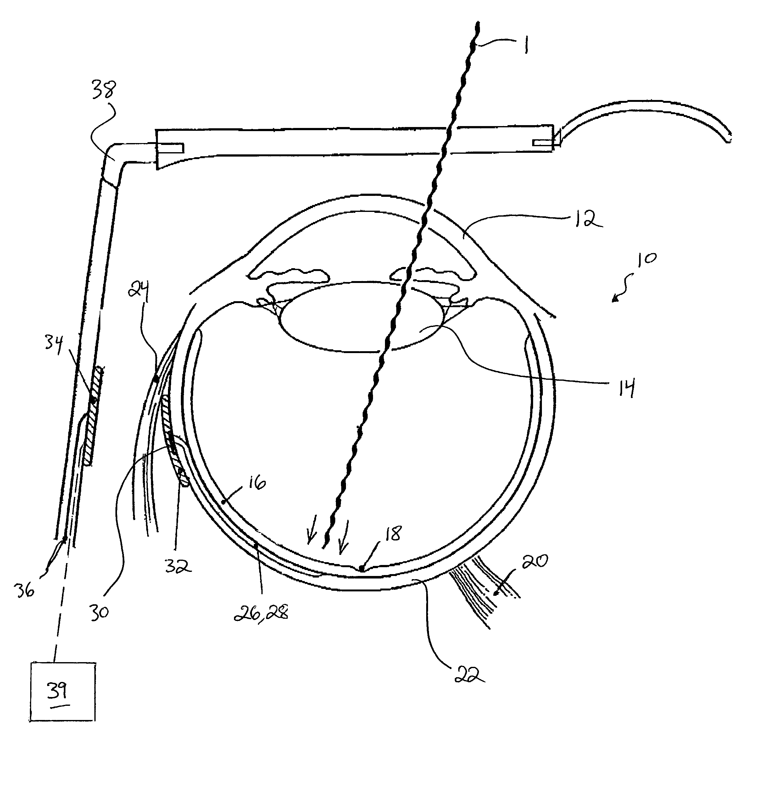
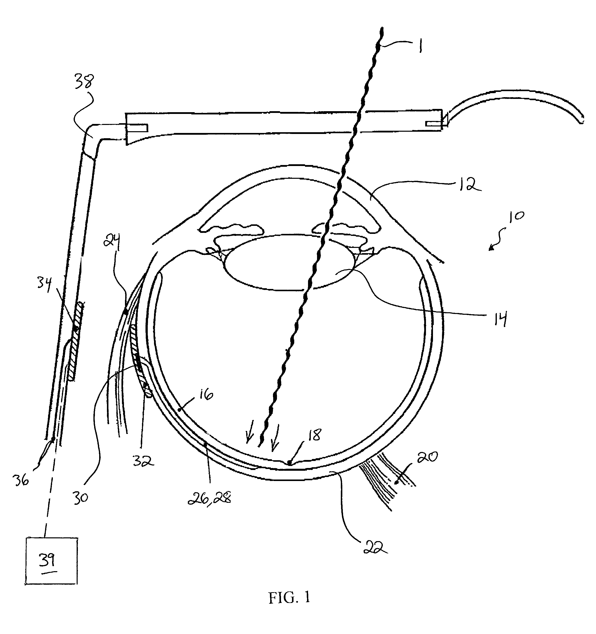
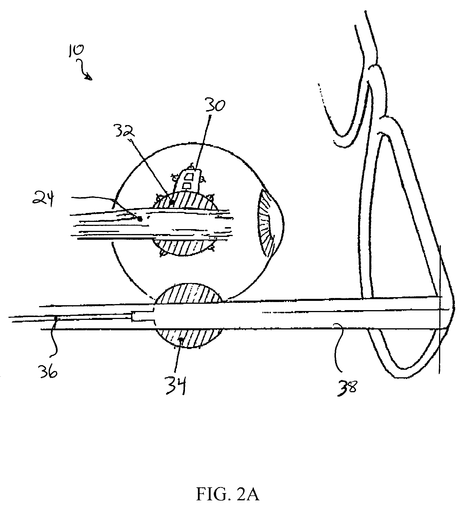
[0028]A retinal prosthesis is disclosed that is designed to emulate the natural workings of the eye (for instance, by using natural light entering the eye to trigger the spatial pattern of nerve stimulation) while also enhancing the biocompatibility (16, 27, 70, 103) of the device by virtue of its low profile, flexible configuration, and implantation almost entirely outside of the eye. The eye is especially prone to inflammation, which over time can be destructive and, in the worse cases, can cause loss of the eyeball. In a preferred embodiment, the present invention utilizes materials and a structure that minimizes the potential for ocular damage. In particular, this present invention seeks to alter the normal anatomy of the eye as little as possible and to remove potentially harmful mechanical and thermal (43, 87) stress from the retina, which is the most delicate element of the eye.

[0029]Enhanced biocompatibility is achieved by placing almost the entire retinal prosthesis outside...


PUM


Abstract

An ocular device that can more safely and effectively perform all functions needed of a retinal prosthesis with electronic components that are placed outside the wall of an eye, are powered wirelessly provided by an external power source, and which provide a patient with a view determined by natural motion of the eye and triggered by natural incident light converging at the retina. In one aspect, the invention is an externally powered, light-activated, sub-retinal prosthesis in which natural light entering the eye conveys visual details to the sub-retinal prosthesis, while wireless radiofrequency transmission provides the power needed to stimulate the retina, which would be insufficient if it were obtained from the intensity of incoming light alone.

Description

CROSS-REFERENCE TO RELATED APPLICATIONS[0001]The present application claims priority to U.S. Provisional Application No. 60 / 349,687, filed Jan. 17, 2002, the teachings of which are incorporated herein by reference.STATEMENT OF GOVERNMENT SUPPORT[0002]This invention was made with government support under Grant Nos. BES-0001296 and BES-0201861, awarded by NIH. The U.S. Government has certain fights in the invention.FIELD OF THE INVENTION[0003]The present invention is directed to the field of ocular devices and more particularly to an apparatus and method for a minimally invasive retinal prosthesis.BACKGROUND OF THE INVENTION[0004]A reference list is appended hereto. Citation numbers identified in parentheses refer to this reference list. All of the teachings of the references identified in the reference list are incorporated herein by reference.[0005]A visual prosthesis is a device that captures aspects of the visual environment and uses this information to stimulate nerves within the...

Claims


Application Information

Patent Timeline
IPC IPC(8): A61F2/14A61F9/08A61N1/05A61N1/36
CPCA61F2/14A61F9/08A61N1/0543A61N1/36046A61N1/3787
Inventor RIZZO, JOSEPH F.WYATT, JR., JOHN L.THEOGARAJAN, LUKE
Owner MASSACHUSETTS EYE & EAR INFARY
Why Eureka
Try Eureka