Biosensor

a biosensor and sensor technology, applied in the field of biosensors, can solve the problem of few successful bioelectronic sensors

Inactive Publication Date: 2005-12-20
DUKE UNIV
View PDF8 Cites 37 Cited by
  • Summary
  • Abstract
  • Description
  • Claims
  • Application Information

AI Technical Summary

Problems solved by technology

One of the main challenges in sensor development is devising materials combining analyte binding diversity with mechanisms that transduce molecular recognition events (Ellis et al, Chem. Rev. 100:2477–2478 (2000), Hellinga et al, Trends Biotechnol.
Few successful bioelectronic sensors have been developed (Boon et al, Nat. Biotechnol. 18:1096–1100 (2000), Cornell et al, Nature 387:580–583 (1997)), however, because most proteins lack the functionalities to establish ligand-mediated electronic communication.

Method used


Image

  • Biosensor
  • Biosensor
  • Biosensor

Examples


example 1

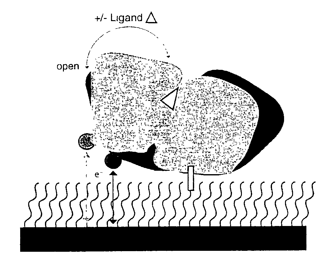
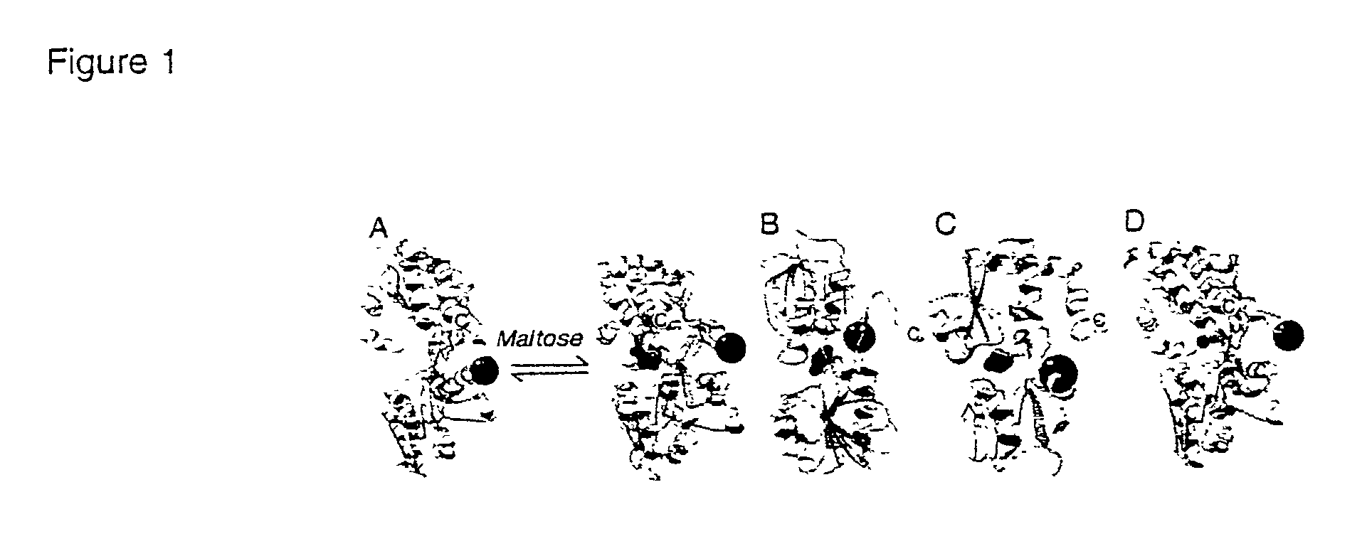
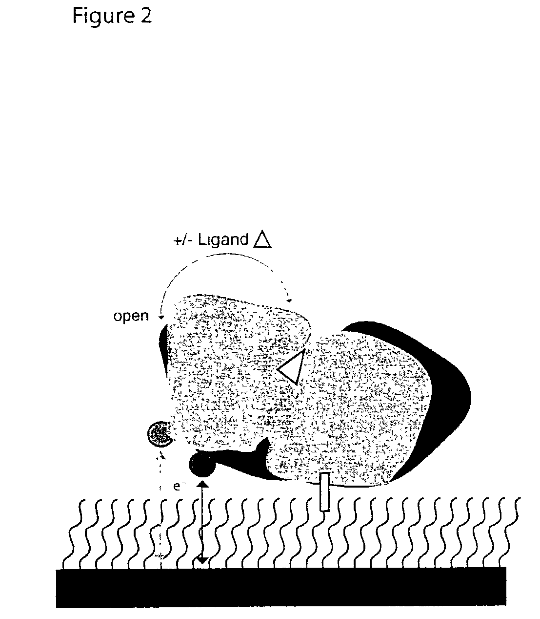
Chemoresponsive Bioelectronic Assemblies

Experimental Details

[0030]Protein purification and labeling. Proteins were produced and labeled as previously reported (Marvin et al, Proc. Natl. Acad. Sci. USA 94:4366–4371 (1997), Marvin et al, J. Am. Chem. Soc. 120:7–11 (1998)). The thiol-reactive Ru(II) reporting group, [Ru(II)(NH3)4(1,10-phenanthroline-5-maleimide)] (PF6) was synthesized as described (Trammell et al, Bioconjug. Chem. 12:643–647 (2001)).

[0031]SAM formation. 1-mm diameter gold disk electrodes were successively polished with 6, 3, and 1-μm diamond paste and sonicated in water for 1 min between each polishing step. SAMs (self-assembled monolayers) were constructed in a manner similar to a previously published procedure (Thomson et al, Biophys. J. 76:1024–1033 (1999)). The polished electrodes were rinsed with water and immediately incubated in a solution of 11-thiolundecanoic acid (5 mM in ethanol or acetonitrile) for 24 h. Electrodes were then activated (COOH group) by immers...


PUM

PropertyMeasurementUnit
pHaaaaaaaaaa
pHaaaaaaaaaa
midpoint reduction potentialaaaaaaaaaa

Abstract

The present invention relates, in general, to biosensors and, in particular, to bioelectronic sensors comprising a macromolecule immobilized on an electrode surface so that a redox cofactor that is site-specifically attached to the surface of the macromolecule is between the macromolecule and electrode surface ligand-mediated conformational changes alter the geometry of interaction between the redox cofactor and the electrode surface resulting in a change in electronic coupling between the cofactor and electrode.

Description

[0001]This application claims priority from Provisional Application No. 60 / 315,036, filed Aug. 28, 2001, the entire content of which is incorporated herein by reference.TECHNICAL FIELD[0002]The present invention relates, in general, to biosensors and, in particular, to bioelectronic sensors and methods of using same in analyte detection.BACKGROUND[0003]Chemoresponsive sensors have numerous medical, environmental, and defense applications (Ramsay (ed.) Commercial Biosensors: Applications to Clinical, Bioprocess, and Environmental Samples (John Wiley & Sons, New York (1998)). One of the main challenges in sensor development is devising materials combining analyte binding diversity with mechanisms that transduce molecular recognition events (Ellis et al, Chem. Rev. 100:2477–2478 (2000), Hellinga et al, Trends Biotechnol. 16:183–189 (1998)). Bioelectronic interfaces (Wilner et al, Agnew. Chem. mt. Ed 39:1180–1218 (2000), Ottovaleitmannova et al, Frog. Surf Sci. 41:337–445 (1992), Gopel,...

Claims


Application Information

Patent Timeline
Patent Type & Authority Patents(United States)
IPC IPC(8): G01N27/327C12Q1/02G01N27/416G01N33/543
CPCB82Y15/00B82Y30/00G01N33/54306G01N33/5438G01N33/66Y10S436/815Y10S436/806
Inventor HELLINGA, HOMME W.CONRAD, DAVID W.BENSON, DAVID E.
Owner DUKE UNIV
Why Eureka
Try Eureka