DC-DC converter

a dc converter and converter technology, applied in the direction of dc-dc conversion, power conversion systems, instruments, etc., can solve the problems of low voltage conversion efficiency, high power loss caused by switching elements, inductive elements, other low-resistance components, etc., to improve the voltage conversion efficiency of dc—dc converter, small current through inductive elements, and improve efficiency

Active Publication Date: 2005-12-20
TEXAS INSTR INC
View PDF13 Cites 85 Cited by
  • Summary
  • Abstract
  • Description
  • Claims
  • Application Information

AI Technical Summary

Benefits of technology

[0005]In order to improve the voltage conversion efficiency of the DC—DC converter, a system that divides the voltage increase / decrease operation is proposed. In other words, the operation of the switching regulator is divided into the operation that stores energy in the inductive element from the power supply voltage, and the operation that outputs the magnetic energy stored in the inductive element as current to the load. When the voltage increase / decrease operation is divided into two operating modes for voltage increase and voltage decrease, the input side or output side is connected at a 100% duty ratio. Therefore, the current through the inductive element becomes small, and the efficiency can be improved.

Problems solved by technology

As a result, the power loss caused by the switching element, inductive element, and other low-resistance components becomes high, and the voltage conversion efficiency is low.

Method used


Image

  • DC-DC converter
  • DC-DC converter
  • DC-DC converter

Examples


Embodiment Construction

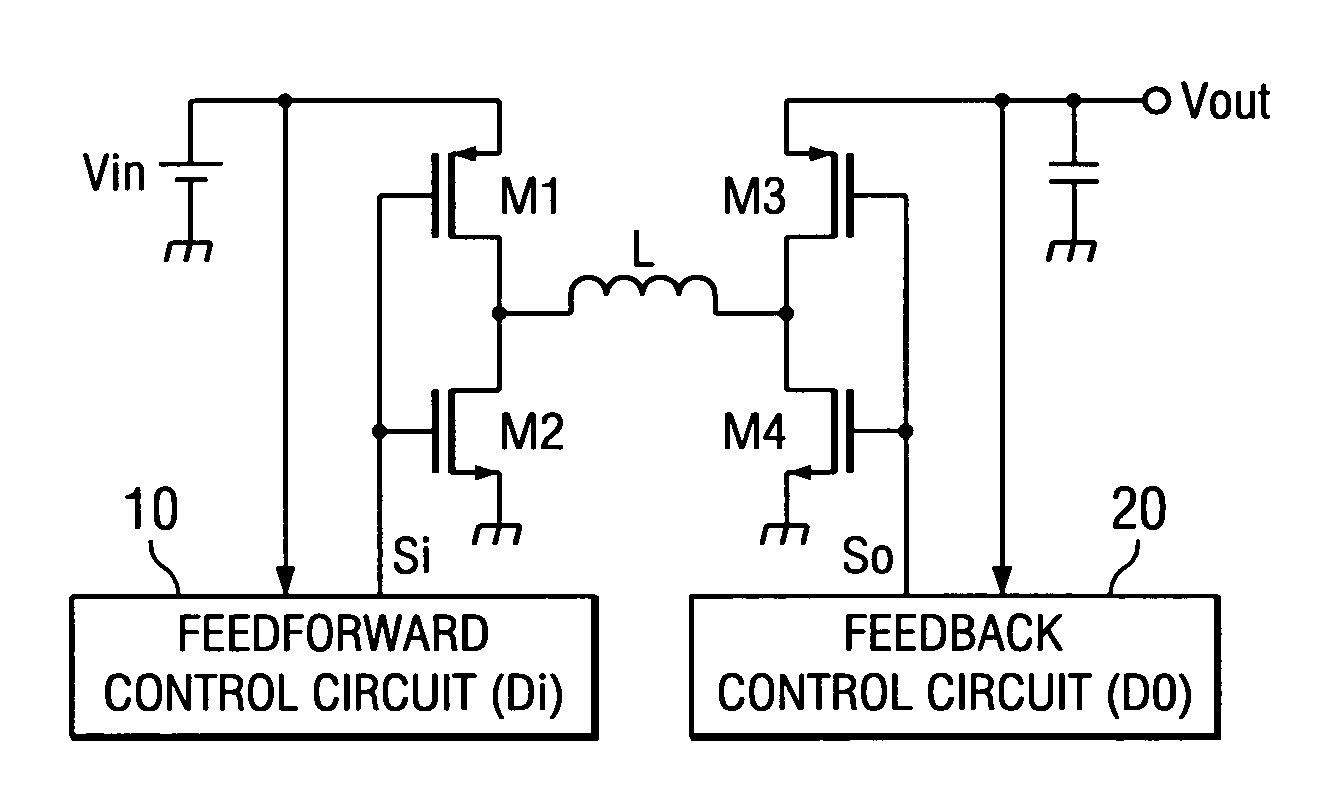
[0022]FIG. 1 is a circuit diagram illustrating the basic configuration of the DC—DC converter disclosed in the present invention.

[0023]As shown in the figure, the DC—DC converter of the present invention has the configuration of a so-called H bridge type switching regulator. The H bridge type switching regulator, as shown in the figure, includes an inductive element L (referred to as inductor L hereinafter) and four switching elements connected to the two terminals of inductor L. The switching elements, for example, comprise MOS transistors. They can also comprise bipolar transistors instead of MOS transistors.

[0024]In the example shown in FIG. 1, switching elements M1 and M3 comprise PMOS transistors, while switching elements M2 and M4 comprise NMOS transistors. As shown in the figure, switching element M1 is connected between the supply side of power supply voltage Vin and one terminal Tx of inductor L. Switching element M2 is connected between the terminal Tx of inductor L and gr...


PUM


Abstract

A DC—DC converter can supply a stable output voltage from an input voltage with the power supply voltage varying along with the supply of the power and can maintain a high voltage conversion efficiency. The DC—DC converter includes an inductive element and the first-fourth switches connected to both terminals of the inductive element, the first and second switches are turned on and off periodically corresponding to the input voltage. When the input voltage goes below a prescribed reference level, a first control signal that keeps the first switch constantly on is generated by a feedforward control circuit to turn on the third and fourth switches periodically corresponding to the output voltage so that the output time of the third switch is generated by a feedback control circuit to switch the voltage increasing operation and the voltage increasing/decreasing operation corresponding to the input voltage.

Description

FIELD OF THE INVENTION[0001]The present invention pertains to a DC—DC converter that can supply the desired DC voltage from the power supply voltage.BACKGROUND OF THE INVENTION[0002]Switching regulators are DC—DC converters that supply a certain voltage independent of changes in the input voltage and can be categorized as the step-up type, which outputs a voltage higher than the input voltage; the step-down type, which outputs a voltage below the input voltage; and the step-up / step-down type. The so-called H-bridge type is also generally known as the voltage step-up / step-down type of switching regulator.[0003]An H-bridge type switching regulator includes an inductive element used for storing magnetic energy, a switching element for controlling the current supply to the inductive element from the power supply voltage, and another switching element for controlling the current output from the inductive element to the load. By controlling the timing for turning each switching element on...

Claims


Application Information

Patent Timeline
Patent Type & Authority Patents(United States)
IPC IPC(8): H02M3/155G05F1/59H02M3/158
CPCH02M3/1582
Inventor NOGAWA, MASASHITATEISHI, TETSUO
Owner TEXAS INSTR INC
Why Eureka
Try Eureka