
Photo-Coupler Device

a photo-coupler and photo-coupler technology, applied in the field of photo-coupler devices, can solve the problems of poor voltage conversion efficiency and common-mode transient resistance, inaccurate reception signals, and easy reduction of electrical conductivity of the photo-coupler structure, and achieve low resistance values, good transmittance, and good voltage conversion efficiency

Active Publication Date: 2014-01-02
VISHAY CAPELLA MICROSYST TAIWAN LTD
View PDF4 Cites 1 Cited by
  • Summary
  • Abstract
  • Description
  • Claims
  • Application Information

AI Technical Summary

Benefits of technology

This patent is about a new photo-coupler device that has several advantages. First, it uses a metal layer made of silver to improve voltage conversion efficiency and immune to common-mode transients. Second, it has a shield layer structure that helps to reduce signal interference by transmitting signals in a differential manner. These improvements make the device better at transmitting signals while minimizing interference.

Problems solved by technology

In addition, since the input and the output of the photo-coupler are isolated from each other, the transmission of the electrical signals has unidirectional characteristics and thus the photo-coupler have a good electrical insulation capability and a noise resisting capability.
Since the optical transmittance and the electrical conductive capability of the indium tin oxide layer is unstable, the electrical conductivity of the photo-coupler structure is easily decreased and the reception signal would be inaccurate caused by the interference of the transient noise.
Further, the electrical resistance of the conventional indium tin oxide layer is large and during a fast signal transmission of the conventional indium tin oxide layer, the voltage conversion efficiency and the common-mode transient resistance become poor, which leads to the distortion problem of the output signal.

Method used


Image

  • Photo-Coupler Device
  • Photo-Coupler Device
  • Photo-Coupler Device

Examples


first embodiment

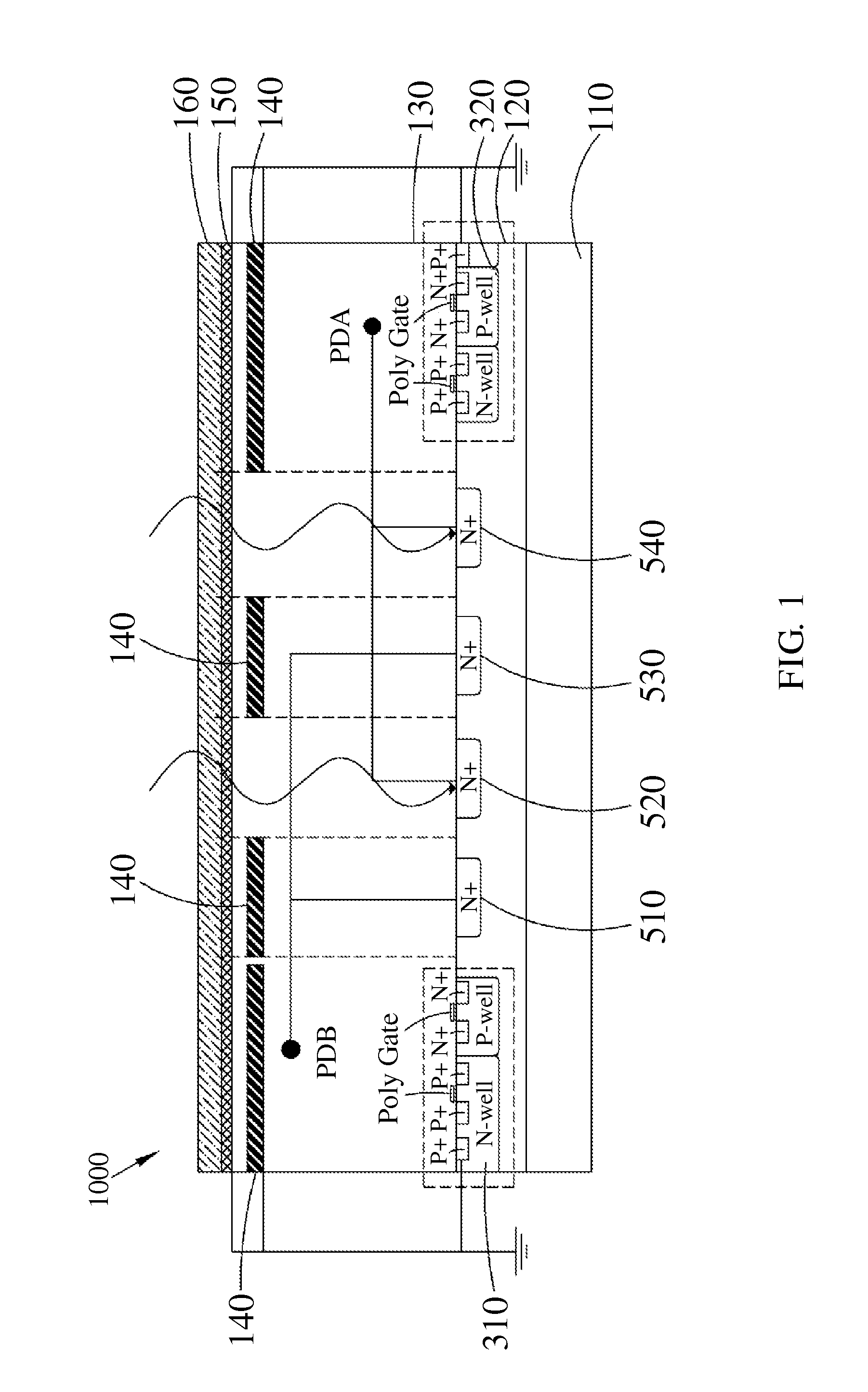
[0036]With reference to FIG. 1, in which a schematic diagram of the photo-coupler device according to the present invention is depicted. In FIG. 1, the photo-coupler device 1000 comprises a P-type substrate 110, a P-type epitaxial layer 120, an insulating layer 130, a plurality of shielding layers 140, a metal layer 150 and a passivation layer 160. The P-type epitaxial layer 120 is deposited on the P-type substrate 110. The insulating layer 130 is deposited on the P-type epitaxial layer 120. The shielding layers 140 are deposited on the insulation layer 130 in a transverse juxtaposition manner. The metal layer 150 is deposited on the insulation layers 140. The passivation layer 160 is deposited on the metal layer 150.

[0037]The P-type epitaxial layer 120 further comprises two conducting regions 310, 320 and a plurality of N+ electrode regions between the two conducting regions 310, 320, and in which at least a portion of the shielding layers 140 is correspondingly arranged for coveri...

second embodiment

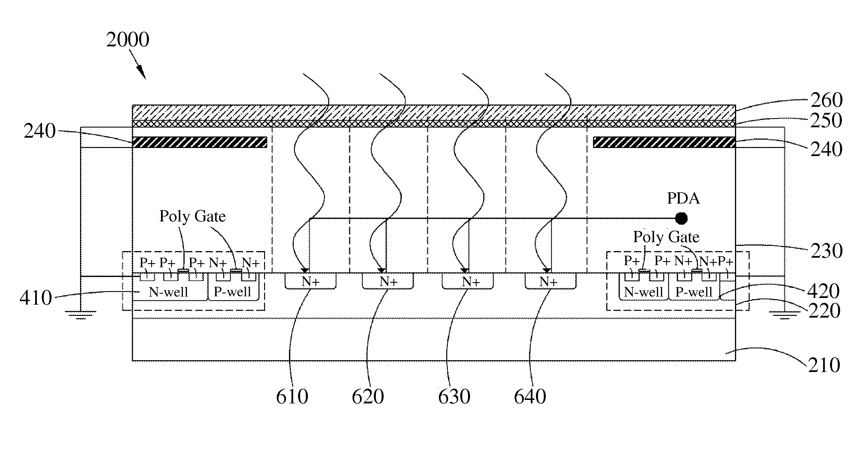
[0045]With reference to FIG. 3, in which a schematic diagram of the photo-coupler device according to the present invention is depicted. In the embodiment, the photo-coupler device 2000 comprises a P-type substrate 210, a P-type epitaxial layer 220, an insulating layer 230, a plurality of shielding layers 240, a metal layer 250 and a passivation layer 260. The P-type epitaxial layer 220 is deposited on the P-type substrate 210. The insulating layer 230 is deposited on the P-type epitaxial layer 220. The shielding layers 240 are deposited on the insulation layer 230 in a transverse juxtaposition manner. The metal layer 250 is deposited on the insulation layers 240. The passivation layer 260 is deposited on the metal layer 250.

[0046]According to the above, the P-type epitaxial layer 220 further comprises two conducting regions 410, 420 and a plurality of N+ electrode regions between the two conducting regions 410, 420. Wherein, the plurality of shielding layers 240 correspondingly cov...


PUM


Abstract

A photo-coupler device includes a P-type substrate, a P-type epitaxial layer, an insulation layer, a plurality of shielding layers, a metal layer and a passivation layer. The P-type epitaxial layer is deposited on the P-type substrate and including two conducting regions and a plurality of N+ electrode regions between the two conducting regions. The insulation layer is deposited on the P-type epitaxial layer. The shielding layers are deposited in the insulation layer in a transverse juxtaposition manner, and the portion of the shielding layers is arranged for correspondingly covering the two conducting regions, another portion of the shielding layers is arranged for correspondingly covering the part of the N+ electrode regions. The metal layer is made of Ag and is deposited on the insulation layer. The passivation layer is deposited on the metal layer.

Description

CROSS-REFERENCE TO RELATED APPLICATION[0001]This application is a non-provisional of U.S. Provisional Application No. 61 / 667,414, filed on Jul. 2, 2012, the disclosure of which is incorporated herein in its entirety by reference.BACKGROUND OF THE INVENTION[0002]1. Field of the Invention[0003]The present invention generally relates to a photo-coupler device, in particular to a photo-coupler device with improved light transmittance and common-mode transient immunity.[0004]2. Description of the Related Art[0005]Photo-coupler is also known as an optical isolator, and abbreviated as PC. The photo-coupler transmits electrical signals by using light as a medium. The photo-coupler has a prefect isolation effect for the input signal and the output signal, and may obtain a wide range of applications in a variety of circuits.[0006]Currently, the photo-coupler has become one of the most popular and the most versatile photoelectric devices. The photo-coupler generally consists of three portions:...

Claims


Application Information

Patent Timeline
IPC IPC(8): H01L31/12
CPCH01L31/125H01L31/173H03K17/78
Inventor SHIH, CHENG-CHUNGLIN, YUH-MINTSANG, KOON-WING
Owner VISHAY CAPELLA MICROSYST TAIWAN LTD
Learn More