Thin-film piezoelectric resonator and method for fabricating the same

a piezoelectric resonator and thin film technology, applied in the direction of piezoelectric/electrostrictive/magnetostrictive devices, electrical apparatus, impedence networks, etc., can solve the problems of electric loss and a lot of technical problems

Active Publication Date: 2005-12-20
SNAPTRACK
View PDF12 Cites 67 Cited by
  • Summary
  • Abstract
  • Description
  • Claims
  • Application Information

AI Technical Summary

Benefits of technology

[0014]A second feature of the invention is to provide a thin-film piezoelectric resonator, a filter and a dupluxer with small ripples, and a method for fabricating the thin-film piezoelectric resonator, the filter and the dupluxer.

Problems solved by technology

In the present circumstances, however, there still remain a lot of technical problems in order to apply the surface acoustic wave filter to frequencies of not lower than 2 GHz at which the mobile communication apparatuses will work in the future.
For this reason, when each electrode is too thin, there is a possibility that electric loss may occur.

Method used


Image

  • Thin-film piezoelectric resonator and method for fabricating the same
  • Thin-film piezoelectric resonator and method for fabricating the same
  • Thin-film piezoelectric resonator and method for fabricating the same

Examples


first embodiment

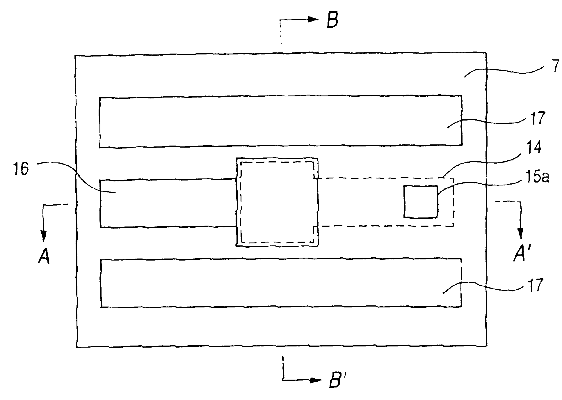
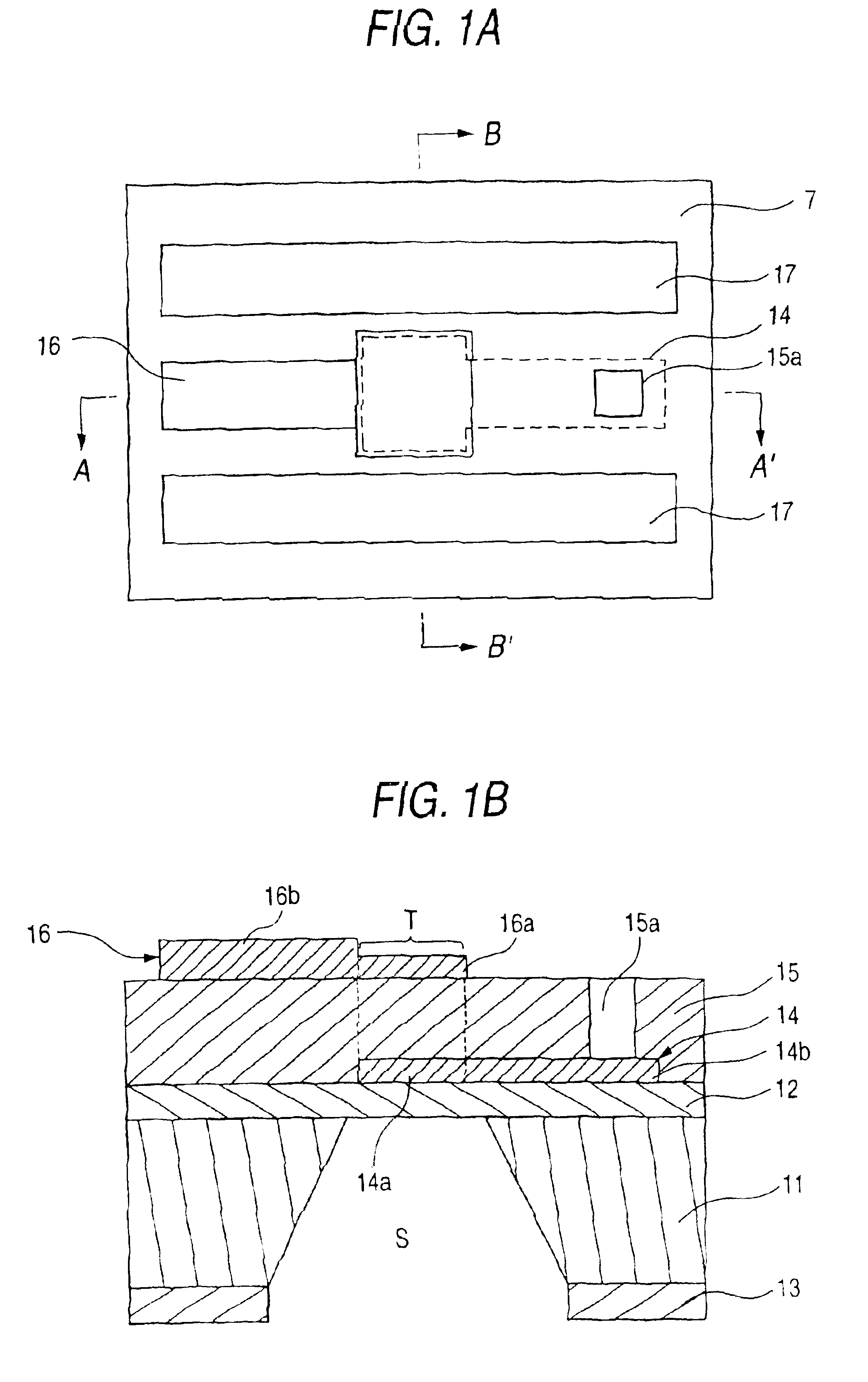
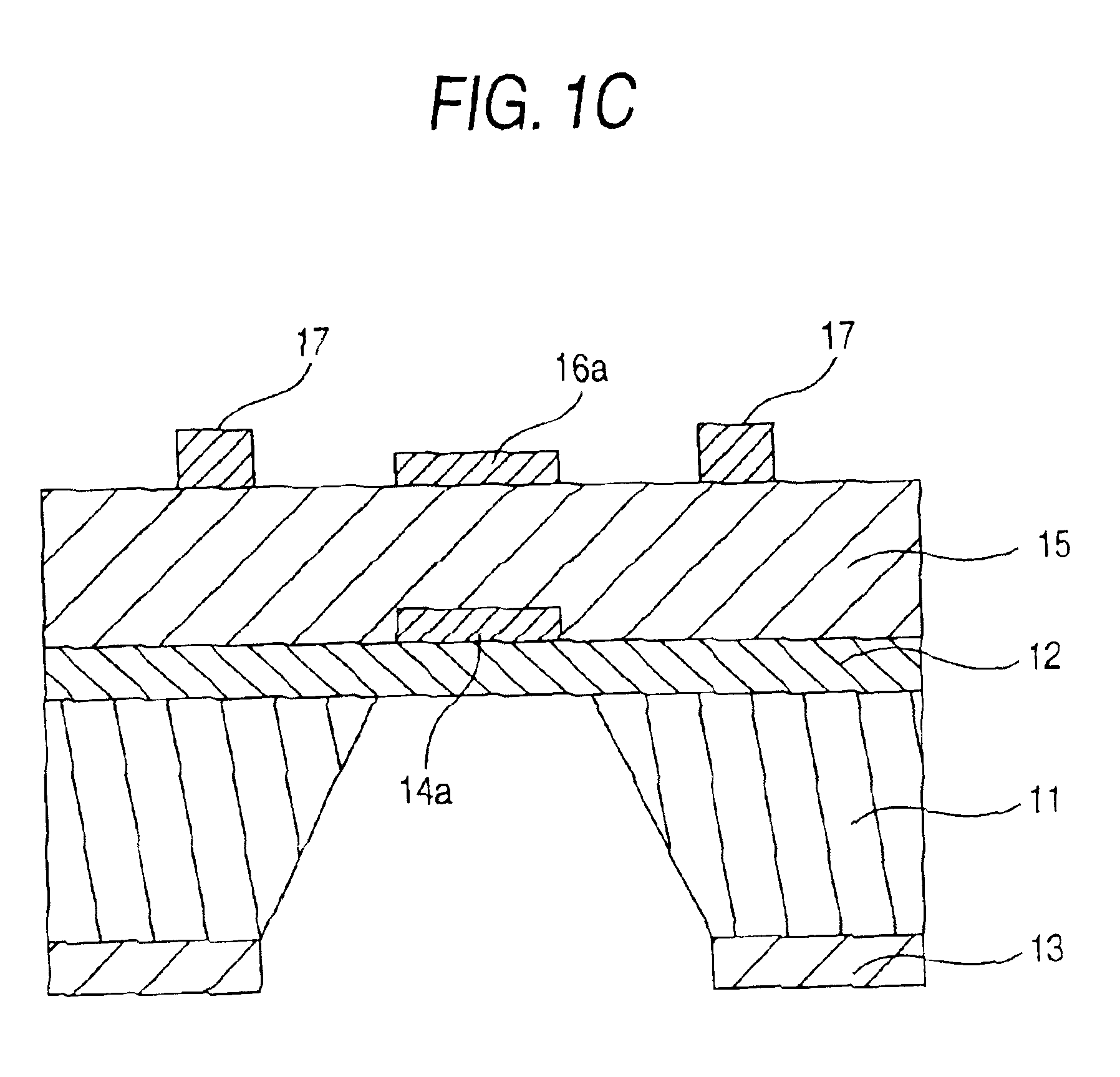
[0039]FIGS. 1A to 1C are schematic views showing a thin-film piezoelectric resonator according to the invention. FIG. 1A is a plan view of the thin-film piezoelectric resonator. FIGS. 1B and 1C are sectional views taken along the line A-A′ and the line B-B′ in FIG. 1A.

[0040]The resonator according to this embodiment includes a substrate 11 having a vibration space S, and an upper barrier layer 12 and a lower barrier layer 13 provided on upper and lower surfaces of the substrate 11 respectively. The resonator further includes a lower electrode 14 provided on the upper barrier layer 12, a piezoelectric thin film 15 provided on the lower electrode 14, and an upper electrode 16 and ground electrodes 17 provided on the piezoelectric thin film 15. The lower electrode is electrically connected to a signal electrode through a through-hole 15a provided in the piezoelectric thin film to thereby form a resonator of a coplanar structure.

[0041]The upper electrode 16 and the lower electrode 14 ha...

second embodiment

[0054]FIGS. 2A and 2B are schematic views showing a filter according to the invention. FIG. 2A is a plan view of the filter. FIG. 2B is a sectional view taken along the line A-A′ in FIG. 2A. The filter is formed as a ladder filter in which resonators are connected in series and in parallel as shown in FIG. 3.

[0055]The basic layer structure or the like is the same as in the first embodiment shown in FIGS. 1A and 1B. Although the description of duplicated parts will be omitted here, the structure of electrodes as a different structure will be described below.

[0056]Lower electrodes 24A and 24B are disposed left and right in FIGS. 2A and 2B. A lower electrode 24C is disposed below the lower electrodes 24A and 24B in FIG. 2A. Each of the lower electrodes 24A and 24B is substantially shaped like a rectangle in plan view so that the width of a neighborhood of an end portion of the lower electrode adjacent to an end portion of the other lower electrode is slightly larger than the width of t...

third embodiment

[0076]FIGS. 5A and 5B are schematic views showing a thin-film piezoelectric resonator according to the invention. FIG. 5A is a plan view of the thin-film piezoelectric resonator. FIG. 5B is a sectional view taken along the line A-A′ in FIG. 5A.

[0077]The basic layer structure or the like is the same as in the first embodiment shown in FIGS. 1A and 1B. The description of duplicated parts will be omitted. Other parts than an upper electrode, a lower electrode and ground electrodes are not shown in FIGS. 5A and 5B. The structure of electrodes as a different structure will be described below.

[0078]In the resonator according to this embodiment, at least one of the upper electrode 34 and the lower electrode 36 is formed so that the electrode material of the resonant portion 34a (36a) is different from the electrode material of the lead-out portion 34b (36b) formed to be continued from the resonant portion 34a (36a).

[0079]The resonant portion and the lead-out portion are connected to each o...


PUM


Abstract

A thin-film piezoelectric resonator including a piezoelectric thin film having piezoelectric characteristic, and an upper electrode and a lower electrode arranged on opposite surfaces of the piezoelectric thin film for applying an excitation voltage to the piezoelectric thin film, wherein: each of the upper electrode and the lower electrode includes a resonant portion, and a lead-out portion; and the electrode thickness of at least one part of the lead-out portion in at least one of the upper electrode and the lower electrode is larger than the electrode thickness of the resonant portion formed to be continued from the lead-out portion.

Description

BACKGROUND OF THE INVENTION[0001]The present invention relates to a thin-film piezoelectric resonator, a filter and a duplexer including such piezoelectric resonators, and a method for producing the thin-film piezoelectric resonator.[0002]In mobile communication apparatuses such as cellular phones which have come into wide use recently, both reduction in size and heightening in operating frequency have advanced year by year. Therefore, both reduction in size and heightening in operating frequency have been required in electronic parts used in such mobile communication apparatuses.[0003]Some mobile communication apparatuses have a duplexer for performing switching between a transmit signal path and a receive signal path in order to use one antenna for both transmission and reception. The duplexer has a transmit filter capable of passing a transmit signal but cutting off a receive signal, and a receive filter capable of passing a receive signal but cutting off a transmit signal.[0004]...

Claims


Application Information

Patent Timeline
Patent Type & Authority Patents(United States)
IPC IPC(8): H03H3/02H03H3/04H03H9/02H03H9/17H03H9/56H03H9/58H03H9/70
CPCH03H3/04H03H9/02094H03H9/02149H03H9/173H03H9/174H03H9/564H03H2003/0428
Inventor KOMURO, EIJUIMURA, MASAAKIGUNJI, KATSUHIKOTAKEISHI, TAKUWHATMORE, ROGER WILLIAMSOUTHIN, JOSEPH EDWARD ALBERT
Owner SNAPTRACK
Why Eureka
Try Eureka