Multi-directional pressure-responsive input device

Active Publication Date: 2005-12-20
ALPS ALPINE CO LTD
View PDF18 Cites 11 Cited by
  • Summary
  • Abstract
  • Description
  • Claims
  • Application Information

AI Technical Summary

Benefits of technology

[0036]The present invention has been made in view of the above problems, and an object of the invention is to provide an input device that enhances the reliability and extends the life, facilitates the setting of multi-functions and replacements if found defective, and reduces the power consumption.
[0038]This construction brings the elastic bodies made of rubber or the like into contact with the resistors on the lower sheet with interventions of the upper sheet and the conductors, whereby the abrasion of the elastic bodies is reduced, and the life thereof is prolonged to enhance the reliability. Further, it does not need a conductive rubber, thus leading to lowering the production cost.
[0040]This construction allows the detection of slant directional operations as well as the detection of up, down, right, and left directional operations, and also the detection of the force strength when operated, which achieves a control that a user can easily manipulate.
[0042]Thanks to this construction, the controller switches the status into the second mode when the operation member is not operated for a predetermined period of time, in which the voltage is not applied to the resistors, thus reducing the power consumption.
[0046]Thanks to this construction, the members for inputting operational directions and the members for key inputs can be integrally formed, which contributes to reducing the production cost. Since the members for key inputs are constructed only inside the upper and lower films, the construction is very resistant to corrosions to contribute to high reliability and a prolonged life of these members, and also facilitates to discover defects.
[0048]This construction gives a user a feeling of click during operation, and the user can confirm secure operation.

Problems solved by technology

However, in this type of input device having the fixed contacts 86a, 86b printed on the printed circuit board 81, there occur wear and smear on the fixed contacts 86a, 86b, which lowers the reliability and shortens the life of the contacts, thus presenting a problem to be solved.
Furthermore, in the circuit to detect the resistances of the resistors, since the controller 98 has to be monitoring the analog voltages inputted to the analog voltage input terminals A / D1 and A / D2, the power consumption increases only to shorten the continuous operational time, which is a problem.

Method used


Image

  • Multi-directional pressure-responsive input device
  • Multi-directional pressure-responsive input device
  • Multi-directional pressure-responsive input device

Examples


Embodiment Construction

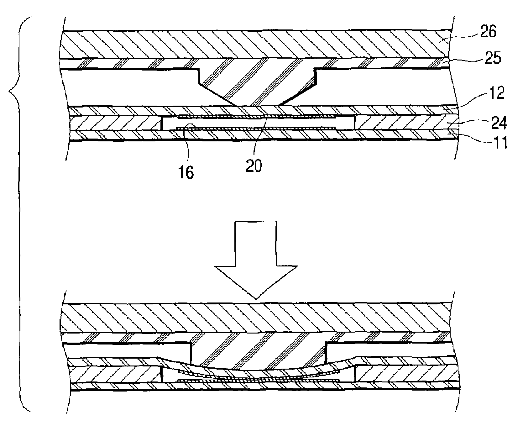
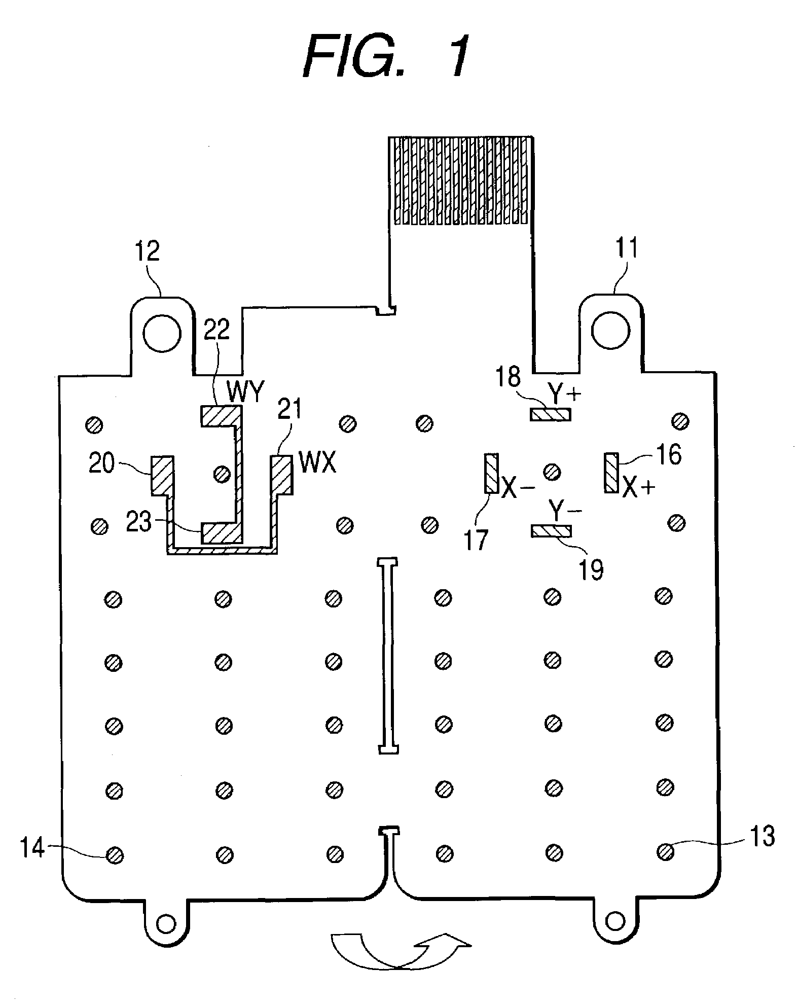
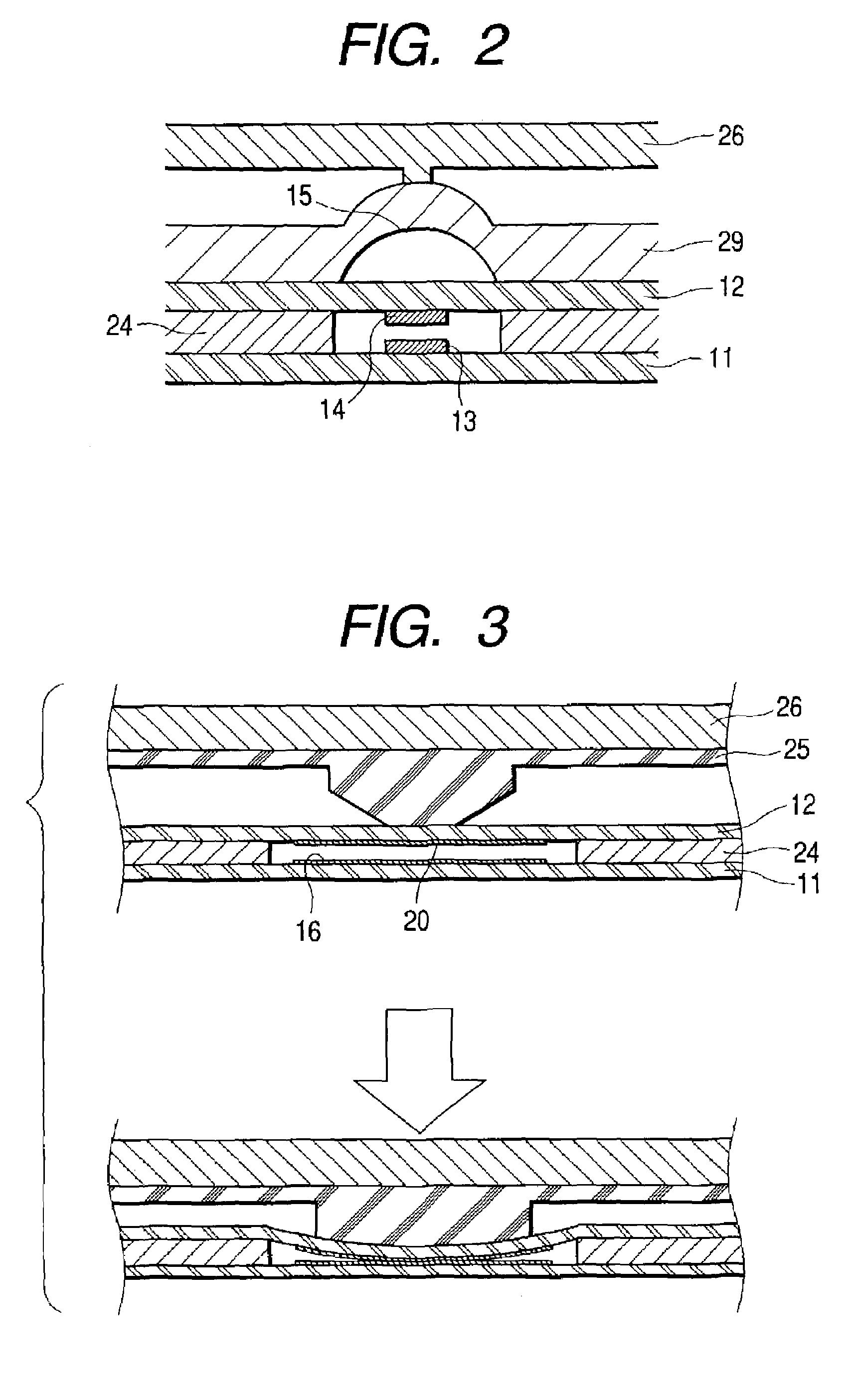
[0062]The preferred embodiment of the input device according to the invention will be described based on FIG. 1 through FIG. 8. FIG. 1 explains the upper and lower sheet of the input device according to the present invention, FIG. 2 illustrates a section of a key switch of the input device according to the present invention, FIG. 3 illustrates a section of the construction to vary the resistance of a resistor of the input device according to the present invention, FIG. 4 illustrates a circuit to detect the resistance of a resistor of the input device according to the present invention, FIG. 5 is a flowchart explaining the operation of a controller of the input device according to the present invention, FIG. 6 illustrates an equivalent circuit in the stop mode of the circuit to detect the resistance of the resistor of the input device according to the present invention, FIG. 7 illustrates an equivalent circuit in the normal mode of the circuit to detect the resistance of the resistor...


PUM

PropertyMeasurementUnit
Angleaaaaaaaaaa
Forceaaaaaaaaaa
Electrical resistanceaaaaaaaaaa

Abstract

The input device of the invention includes: a lower sheet on which four resistors are formed in a manner that each two of them with a center put in between are placed to face each other circumferentially with a spacing of about 90°; an upper sheet overlying the lower sheet with a spacing, on which conductors are formed to face the respective resistors; elastic bodies disposed over the upper sheet to face the respective conductors; and an operation member to retain upper parts of the elastic bodies. And, when the operation member is pressed downward, the elastic bodies are brought into contact with the resistors with interventions of the conductors on the upper sheet.

Description

[0001]This application claims the benefit of priority to Japanese Application 2002-029536, filed on Feb. 6, 2002.BACKGROUND OF THE INVENTION[0002]1. Field of the Invention[0003]The present invention relates to an input device of a mobile electronic apparatus such as a portable telephone, specifically to an input device capable of inputting the direction and strength of a pressing force when a key top (operating member) is pressed.[0004]2. Description of the Related Art[0005]The input device of a conventional portable telephone is made up with a printed circuit board 81, metal contacts 83, a contact sheet 84, and a key top 85, as shown in FIG. 9 and FIG. 10.[0006]The printed circuit board 81 has plural pairs of fixed contacts 86a, 86b printed on the surface thereof, as shown in FIG. 9.[0007]FIG. 10 illustrates the switch structure to put a pair of the fixed contacts 86a, 86b into a conductive state, and the other fixed contacts have the same structure. As shown in FIG. 10, the metal ...

Claims


Application Information

Patent Timeline
IPC IPC(8): G06F3/02G06F3/033G06F3/0338G06F3/038H01H13/702H01H13/712H01H13/785
CPCG06F3/0338H01H13/702H01H13/785H01H2201/036H01H2221/012H01H2239/078H01H2300/022
Inventor ENDO, YOSHIHISANAKAI, TAKASHI
Owner ALPS ALPINE CO LTD
Why Eureka
Try Eureka