Supercharge Your Innovation With Domain-Expert AI Agents!

Pilot signal reception method and receiver

a technology of pilot signal and receiver, applied in the direction of digital transmission, pulse technique, electrical apparatus, etc., can solve the problem of low reliability of providing reception, and achieve the effect of enhancing the flexibility of despreading timings

Inactive Publication Date: 2005-12-20
PANASONIC CORP
View PDF20 Cites 3 Cited by
  • Summary
  • Abstract
  • Description
  • Claims
  • Application Information

AI Technical Summary

Benefits of technology

[0019]That is, the present invention performs irregular reception processing by randomizing reception timings or changing reception timings by adapting reception timings to reception situations as appropriate. This makes the system less susceptible to cyclic or burst-like fading.
[0025]An aspect of a CDMA receiver of the present invention comprises an A / D converter, despreading circuit, random timing generation circuit, reception control circuit and phase / signal intensity detection circuit. This configuration makes reception timings irregular, allowing the system to perform reception less susceptible to cyclic, burst-like fading.
[0026]Another aspect of the CDMA receiver of the present invention comprises a despreading timing determination circuit and a despreading timing retention circuit that retains timings generated by the despreading timing determination circuit and the despreading timing generation circuit changes reception timings based on past despreading timings retained by the despreading timing retention circuit. This configuration allows despreading to be performed at a timing different from the immediately preceding reception timing. Thus, this configuration allows the system to perform reception less susceptible to cyclic fading.
[0027]Furthermore, another aspect of the CDMA receiver of the present invention adopts a configuration that returns the output of the despreading circuit to the despreading timing determination circuit. This configuration makes it possible to determine despreading timings based on the intensity of the despread signal and perform reception that matches the reception situation.
[0028]Furthermore, another aspect of the CDMA receiver of the present invention adopts a configuration comprising a despreading chip number determination circuit and allowing the output of the despreading circuit to be input to the despreading chip number determination circuit. This configuration allows a channel not subjected to data modulation to be demodulated by despreading by an arbitrary number of chips from a certain chip. This enhances the flexibility of despreading timings. It is also possible to adaptively change the number of chips to be despread according to the situation of the propagation path.

Problems solved by technology

As a result, it has been discovered that reception according to this method provides cyclic and burst-like demodulation of pilot symbols, and therefore can provide reception with low reliability at most when the intensity of the signal is reduced due to cyclic fading or burst-like fading.

Method used


Image

  • Pilot signal reception method and receiver
  • Pilot signal reception method and receiver
  • Pilot signal reception method and receiver

Examples


embodiment 1

(Embodiment 1)

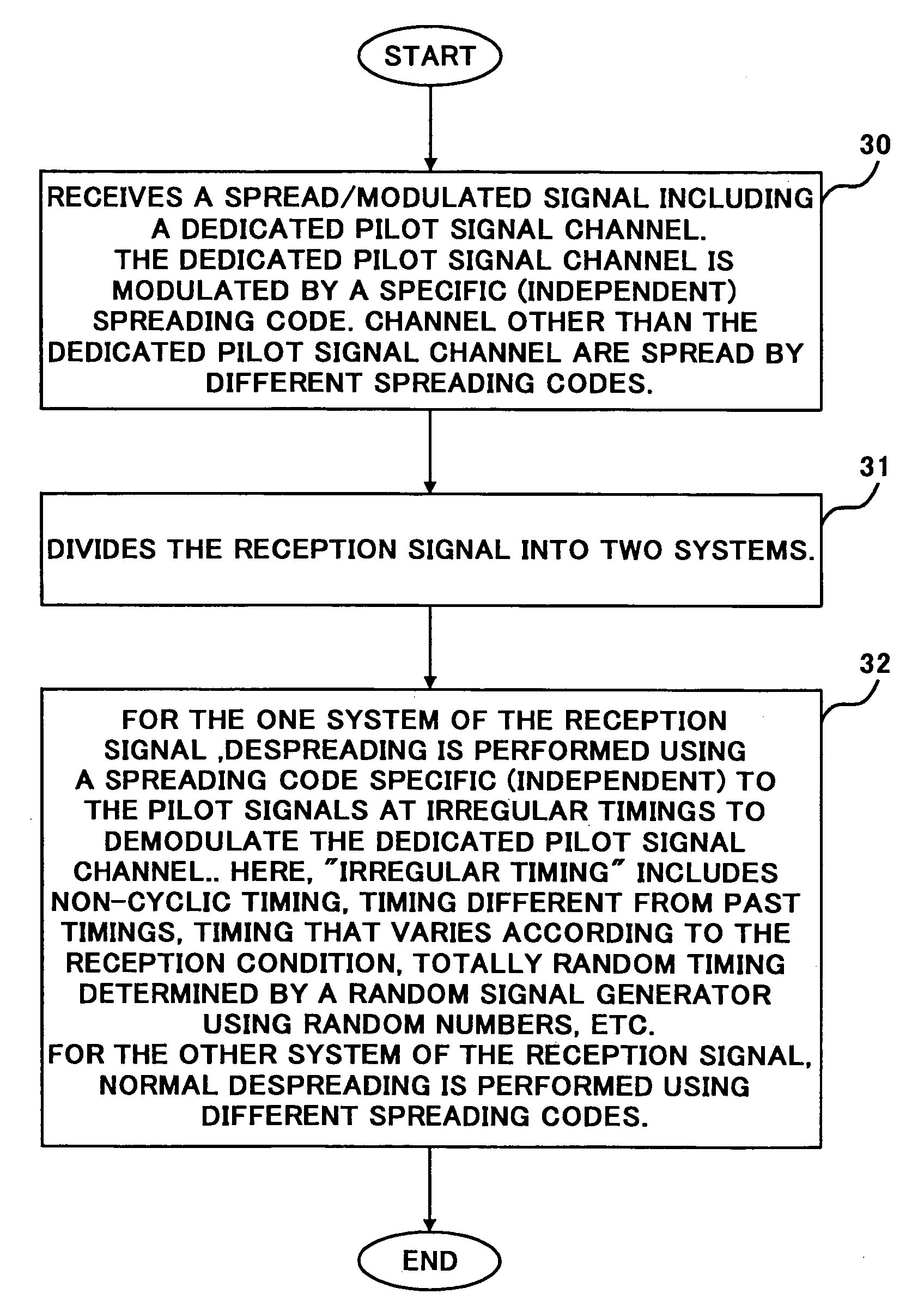
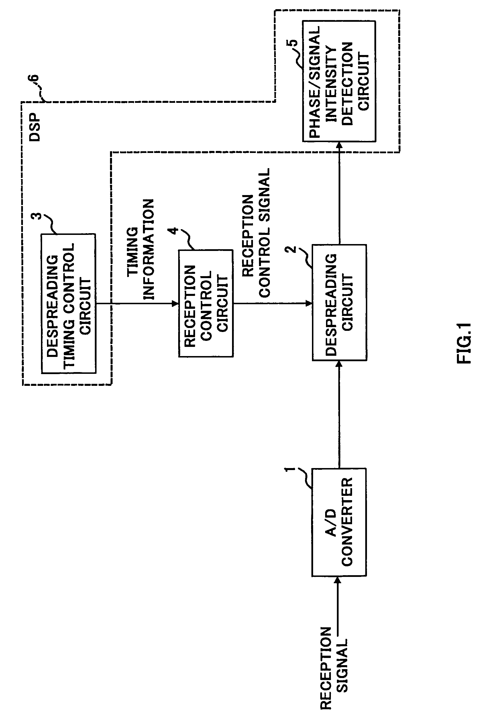
[0049]FIG. 1 is a block diagram showing a main configuration of a CDMA receiver of the present invention.

[0050]As shown in the figure, this CDMA receiver is provided with A / D conversion circuit 1, despreading circuit 2, random timing (irregular timing) determination circuit 3, reception control circuit 4 and phase / signal intensity detection circuit 5.

[0051]In order to perform coherent detection or correct the frequency of a reference clock in a receiver, it is necessary to determine phase variations in reception symbols.

[0052]To determine phase variations in reception symbols, it is necessary to determine variations in the intensity of symbol signals. For this reason, this embodiment is provided with phase / signal intensity detection circuit 5.

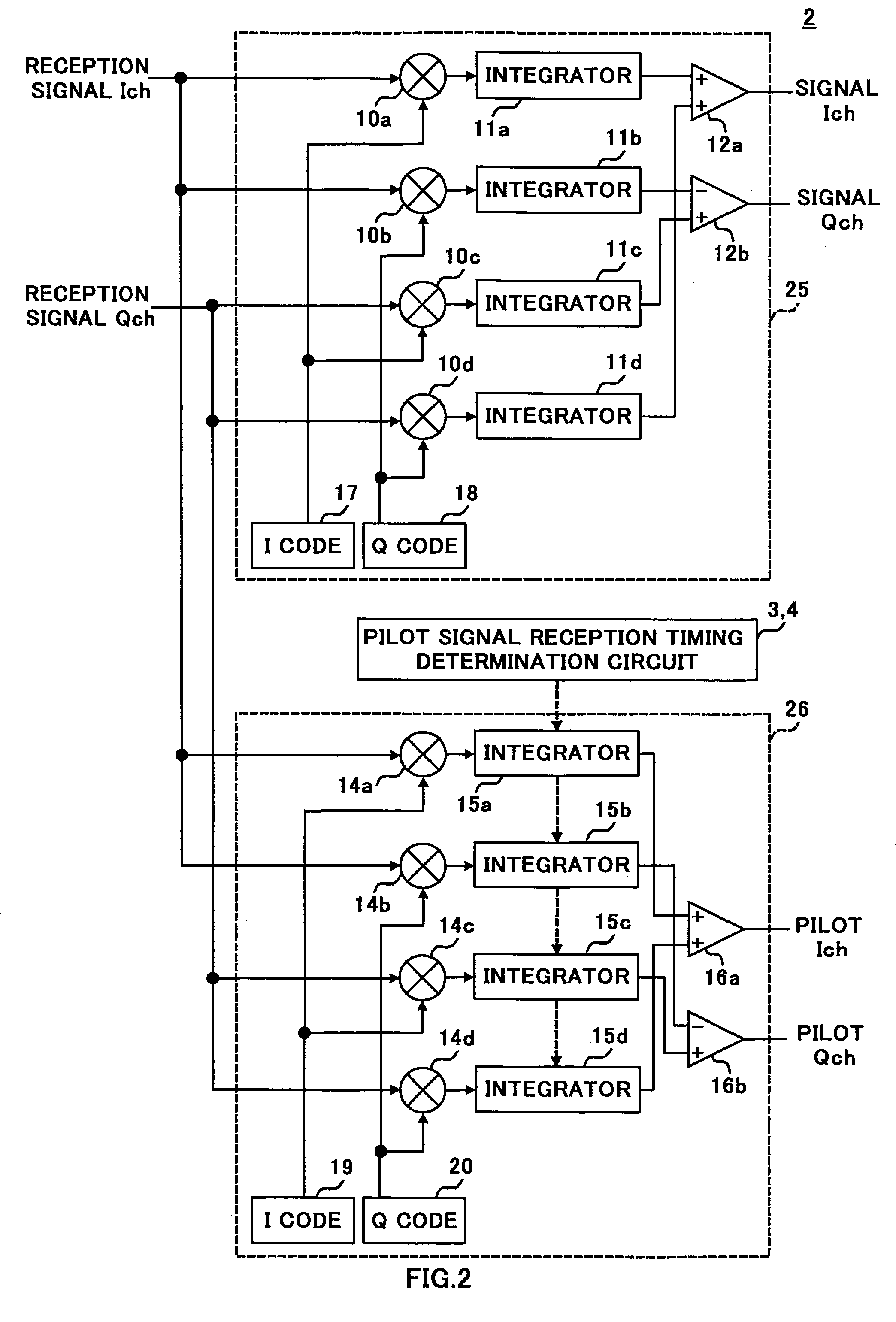
[0053]Synchronization acquisition, creation of a delay profile, correction of the frequency of a reference clock and adjustment of reception timings, etc. are carried out using the signal intensity of pilot symbols (pilot signals)...

embodiment 2

(Embodiment 2)

[0083]FIG. 4 shows another configuration example of the demodulation section of the receiver.

[0084]In this embodiment, a symbol reception timing in a preceding slot is stored. Then, when a symbol reception timing in the next slot is determined, the stored timing or a predetermined period including this timing is designated as a selection prohibition period. Then, symbol reception timings for the next slot are randomly determined.

[0085]First, a reception signal is quantized by A / D converter 51 and input to despreading circuit 52.

[0086]Despreading timing determination circuit 53 generates reception timing information. The timing information is given to reception control circuit 55 and at the same time stored in memory 54.

[0087]The timing information immediately before being stored in memory 54 is returned to timing determination circuit 53.

[0088]When the timing determination circuit determines the next reception timing, the stored timing or a period close to this timing ...

embodiment 3

(Embodiment 3)

[0095]FIG. 6 shows a configuration of the receiver of this embodiment.

[0096]In this embodiment, despreading timings are adaptively changed based on the reception intensity of a demodulated signal after despreading.

[0097]FIG. 6 shows a main configuration of the receiver of this embodiment.

[0098]The output signal of despreading circuit 102 is fed back to despreading timing determination circuit 103 as a monitor signal.

[0099]Despreading timing determination circuit 103 measures the signal intensity of the demodulated signal over a plurality of slots.

[0100]When, the intensity of the reception signal is reduced (that is, reception reliability is lowered) under the influence of cyclic fading seen from the overall demodulation result of a plurality of slots, the period during which the reception intensity is low is designated as a reception prohibition period.

[0101]FIG. 7 shows a reception example.

[0102]There is no problem if sufficient intensity of the demodulated signal is ...


PUM


Abstract

The pilot signal reception method of the present invention irregularly receives pilot symbols. That is, the pilot signal reception method performs irregular reception processing such as randomizing reception timings or changing reception timings according to reception situations as appropriate to reduce influences of fading. Randomization of reception timings is implemented by generating random timings using a random timing generation circuit.

Description

BACKGROUND OF THE INVENTION[0001]1. Field of the Invention[0002]The present invention relates to a pilot signal reception method and receiver.[0003]2. Description of the Related Art[0004]In a CDMA communication, a pilot signal is used to acquire synchronization in a mobile station, create a delay profile and correct frequencies in a mobile station, and adjust reception timings in a mobile station, etc. This pilot signal is sent from a base station.[0005]An IS-95-compliant communication system is provided with a dedicated pilot channel 100 as shown in FIG. 12A.[0006]Furthermore, in a new standard W-CDMA system, a dedicated pilot channel 101 is provided in addition to a channel with pilot signals (PL) inserted at predetermined intervals.[0007]That a dedicated pilot signal channel exists means that pilot signals are output from the transmitting side all the time.[0008]A concrete pilot channel (100 and 101) format example is shown in FIG. 12C.[0009]What is shown in the upper part of FIG...

Claims


Application Information

Patent Timeline
IPC IPC(8): H04B1/76H04B1/10H04B1/707H04B1/7073
CPCH04B1/7097H04B2201/70701H04B1/76
Inventor ANDO, KIMIAKISHINDE, HIROKI
Owner PANASONIC CORP
Features
  • R&D
  • Intellectual Property
  • Life Sciences
  • Materials
  • Tech Scout
  • Unparalleled Data Quality
  • Higher Quality Content
  • 60% Fewer Hallucinations
Learn More