Teller/scanner system and method

a technology of teller/scanner and control machine, which is applied in the field of networked system of controlled machines, can solve the problems of over-processing power, uneconomical use of central processors by low-speed check-processing machines b>100/b>, and burdening multiple host applications with added complexity

a technology of teller/scanner and control machine, which is applied in the field of networked system of controlled machines, can solve the problems of over-processing power, uneconomical use of central processors by low-speed check-processing machines b>100/b>, and burdening multiple host applications with added complexity

US6978455B1Inactive Publication Date: 2005-12-20UNISYS CORP

Image

  • Teller/scanner system and method
  • Teller/scanner system and method
  • Teller/scanner system and method

Examples


Embodiment Construction

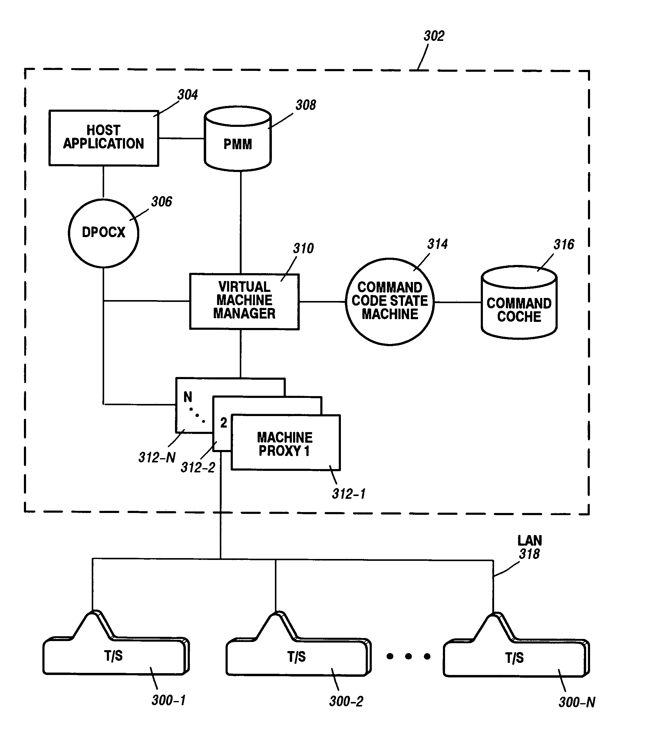
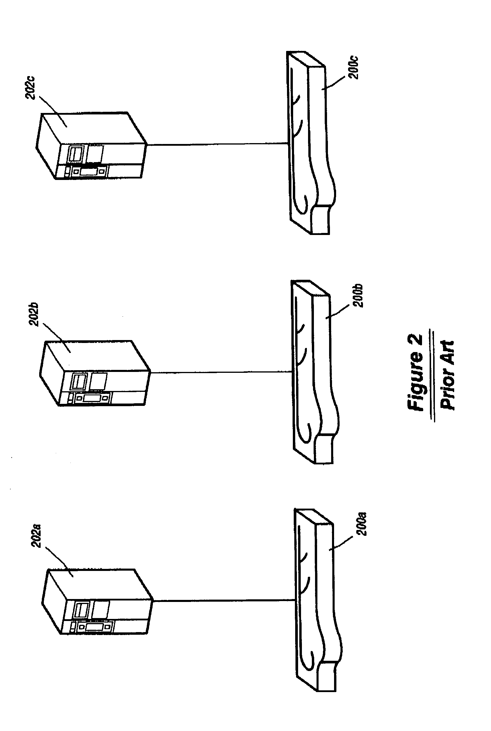
[0017]Referring to FIGS. 2 and 3, one may note the difference between two different types of systems utilizing multiple low-speed check processing machines—a traditional system composed of multiple machines 200a,b,c (FIG. 2) and a system arranged in accordance with the invention using multiple teller / scanner machines 300-1 to 300-N. Note that the traditional system of FIG. 2 requires a separate processor / host application pair 202a,b,c for each check-processing machine 200a,b,c whereas the system of FIG. 3 using the multiple teller / scanners 300-1 to 300-N requires only a single controlling processor 302 with a resident host application 304. Furthermore, the host application 304 controlling the multiple teller / scanner machines can be the same host application that is used to control the older single document processor units 202a,b or c of FIG. 2.

[0018]The object of the invention is to make the multiple teller / scanner machines 300-1 through 300N of FIG. 3 appear as a single input unit ...


PUM


Abstract

A system and method for interfacing a single host application with multiple machines to be controlled by the host application via a local area network minimizes the complexity of dealing with multiple controlled entities by utilizing a single virtual state machine manager communicating with the host application. The virtual machine manager communicates with the controlled machines via machine proxies in conjunction with a command cache state machine and a command cache, which stores previous action requests generated by the host application. A machine epoxy is created for physical controlled entity attached to the system.

Description

[0001]This application claims benefit of provisional application 60 / 101,118, filed Sep. 21, 1998.BACKGROUND OF THE INVENTION[0002]1. Field of the Invention[0003]The invention relates generally to a networked system of controlled machines, such as document processors, sharing a single control processing unit containing a host application for controlling the machines. More particularly, the invention concerns a mechanism for enabling relatively simple communication among a single application program and a plurality of controlled machines, such as document processors.[0004]2. The Prior Art[0005]With reference to FIG. 1, larger, more expensive document processors such as check processor 100 have conventionally been controlled by a dedicated central processing unit 102. This is true regardless of the speed of the check processing machine. Central processor 102 hosts the customer's application software and provides some (or all) of the data manipulation services for check processing machi...

Claims


Application Information

Patent Timeline
20 Dec 2005
Publication
US6978455B1
IPC
G06F9/455; G06F17/00
CPC
G06F9/45558; G06F2009/45595
Inventors
BORKOWSKI, JOSEPH DAVID; MORRIS, WESTON