Automated transmission device with torque transfer, in particular for a motor vehicle

Inactive Publication Date: 2005-12-27
VALEO EMBRAYAGES SAS
View PDF18 Cites 34 Cited by
  • Summary
  • Abstract
  • Description
  • Claims
  • Application Information

AI Technical Summary

Benefits of technology

[0016]The invention thus makes it possible to vary the relative arrangement of the transmission ratios in a transmission

Problems solved by technology

In the known torque-transfer transmission devices, controlling the synchronisation and clutching means is relatively tricky, the declutching having to take place when the driving torque of the driven pinion is substantially zero and the clutching having to take place when the speed of rotation of the driven pinion is equal to that of the driven shaft, so that the means controllin

Method used


Image

  • Automated transmission device with torque transfer, in particular for a motor vehicle
  • Automated transmission device with torque transfer, in particular for a motor vehicle
  • Automated transmission device with torque transfer, in particular for a motor vehicle

Examples


Embodiment Construction

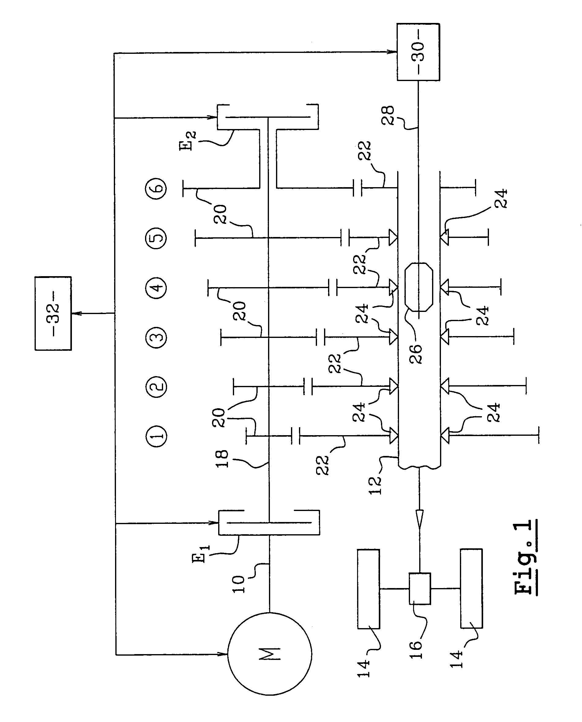
[0041]Reference is made first of all to FIG. 1, which shows schematically a first embodiment of an automatic transmission device with torque transfer according to the invention, intended to connect the output shaft 10 of a thermal engine M, such as in particular an internal combustion engine for a motor vehicle, to a driven shaft 12 which is the output shaft of the device according to the invention and which, in the case of a motor vehicle, is intended to drive driving wheels 14 in rotation by means of a differential 16.

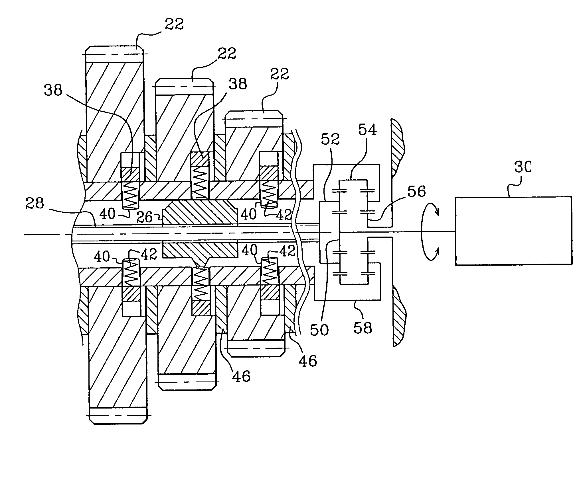
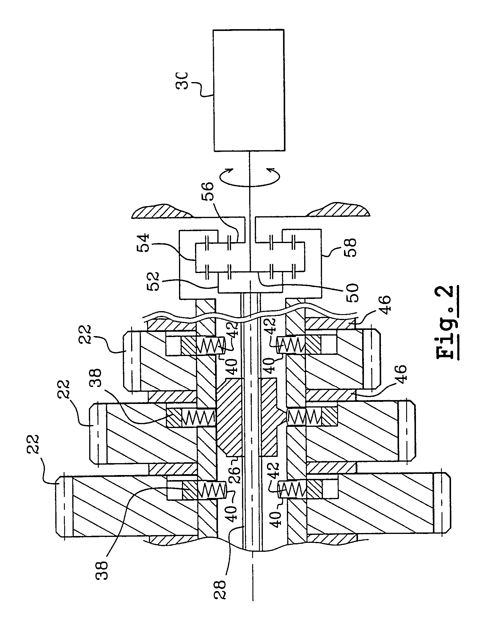
[0042]The device according to the invention comprises an input shaft 18 which is connected to the output shaft 10 of the motor M by a clutch E1. The input shaft 18 is parallel to the output shaft 12 and carries driving pinions 20, each of which is in constant engagement with a driven pinion 22 mounted on the output shaft or driven shaft 12, the pairs of pinions in engagement 20, 22 defining transmission ratios which are numbered from 1 to 6 and which are progressivel...


PUM


Abstract

An automated transmission device with torque transfer having an input shaft (18) that supports drive pinions (20), each of which is engaged with a driven pinion (22) that is mounted freely rotating on a output shaft (12); controlled unidirectional locking mechanism (24) which are mounted between the shaft (12) and the driven pinions (22); and mechanical device for activating the locking mechanisms (24) in a positive manner including at least one cam (26) which translationally moves inside the output shaft (12).

Description

BACKGROUND OF THE INVENTION[0001]The present invention concerns an automatic transmission device with torque transfer, in particular for a motor vehicle, allowing a change in transmission ratio without interruption of a rotation torque between a driving shaft and a driven shaft.DESCRIPTION OF RELATED ART[0002]Transmissions with torque transfer are already known, comprising an input shaft which is connected to a driving shaft by a clutch and which carries driving pinions, a driven shaft which carries driven pinions, each driving pinion being constantly in engagement with a driven pinion and defining a transmission ratio, the driving pinions being rotationally fixed to the input shaft and the driven pinions being free to rotate on the driven shaft and being associated with synchronisation and clutching means which make it possible to selectively connect a driven pinion and the driven shaft, for engaging a given transmission ratio.[0003]One of the driving pinions, for example that of t...

Claims


Application Information

Patent Timeline
IPC IPC(8): F16H3/08F16D21/04F16D41/12F16D48/02F16H3/083F16H3/089F16H3/12F16H61/00
CPCF16D21/04F16D41/12F16H3/083F16H3/12F16H3/089Y10T74/19465F16H2063/3096Y10T74/19279Y10T74/1946
Inventor THERY, PASCAL
Owner VALEO EMBRAYAGES SAS
Why Eureka
Try Eureka