Vertical axis windmill and self-erecting structure therefor

a vertical axis windmill and self-erecting technology, applied in the direction of wind energy generation, wind motors with perpendicular air flow, liquid fuel engine components, etc., can solve the problems of not being able to meet the needs of civil work, the cost of erection and construction, and the least efficient in wind energy gathering ability and transfer. , to achieve the effect of reducing the potential for damage to the overall structure, reducing the risk of damage, and efficient and economical manufacturing

Inactive Publication Date: 2005-12-27
DERMOND +1
View PDF29 Cites 38 Cited by
  • Summary
  • Abstract
  • Description
  • Claims
  • Application Information

AI Technical Summary

Benefits of technology

[0011]In spite of intense work in the field and numerous proposed arrangements to generate electricity from the wind, there is still room for improvement in the design of the overall structure of a windmill, of the blades, of the power unit configuration and in the method for erection thereof

Problems solved by technology

Considering the above, a problem to be solved lies in the requirement that the blades should provide a maximized swept area for a maximal wind catching ability, while simultaneously they must be able to withstand high bending moments and forces.
It has to be considered that on the one hand wind rotors having blades of the most efficient wind catching structure cause t

Method used


Image

  • Vertical axis windmill and self-erecting structure therefor
  • Vertical axis windmill and self-erecting structure therefor
  • Vertical axis windmill and self-erecting structure therefor

Examples


Embodiment Construction

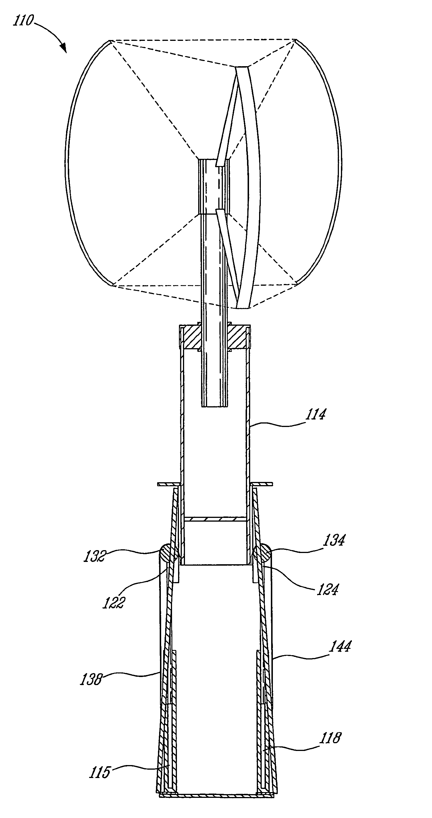
[0044]Generally stated, the present invention provides a structure comprising a blade attachment, a blade structure, an integrated driving shaft / generator for a wind system such as a vertical axis windmill, and a self erecting structure for such a wind system, together with an erecting method thereof.

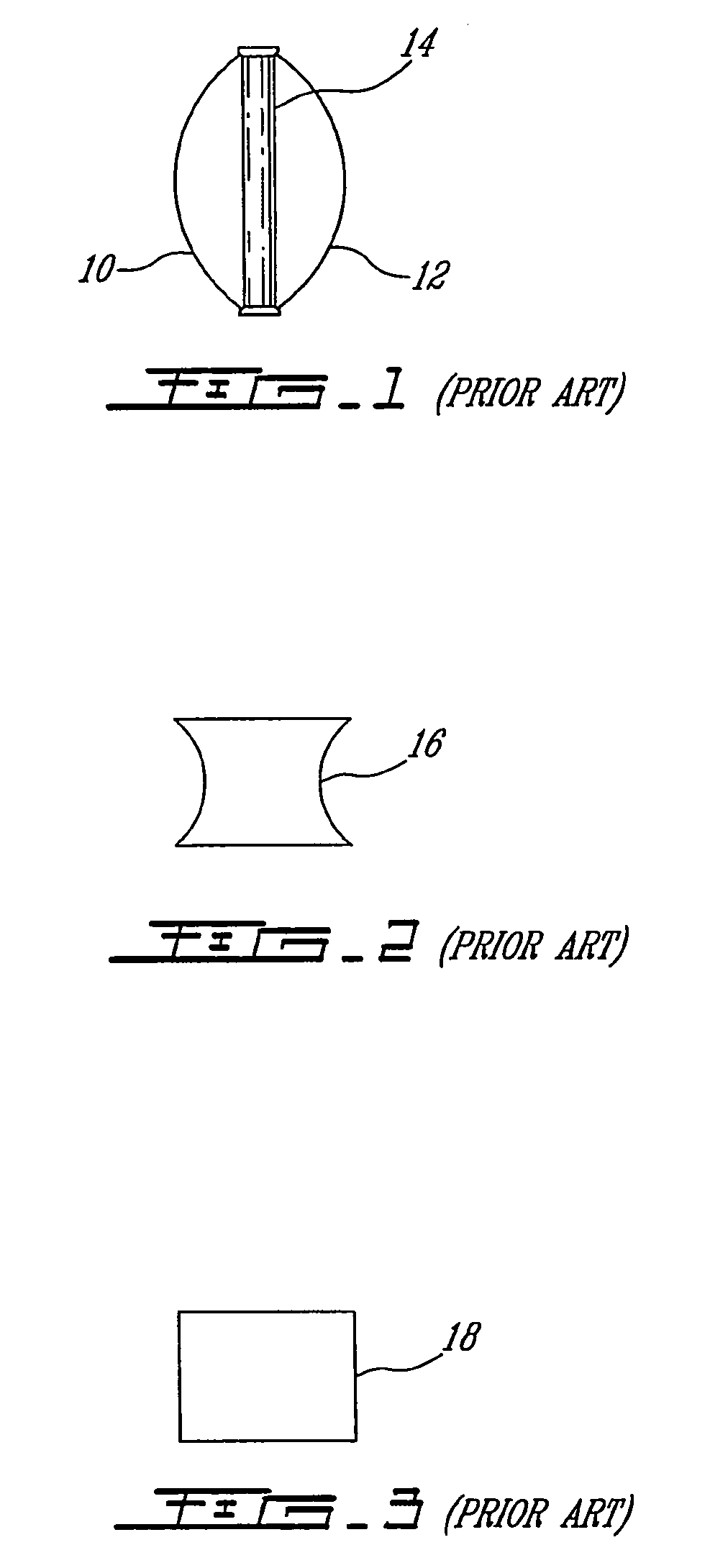
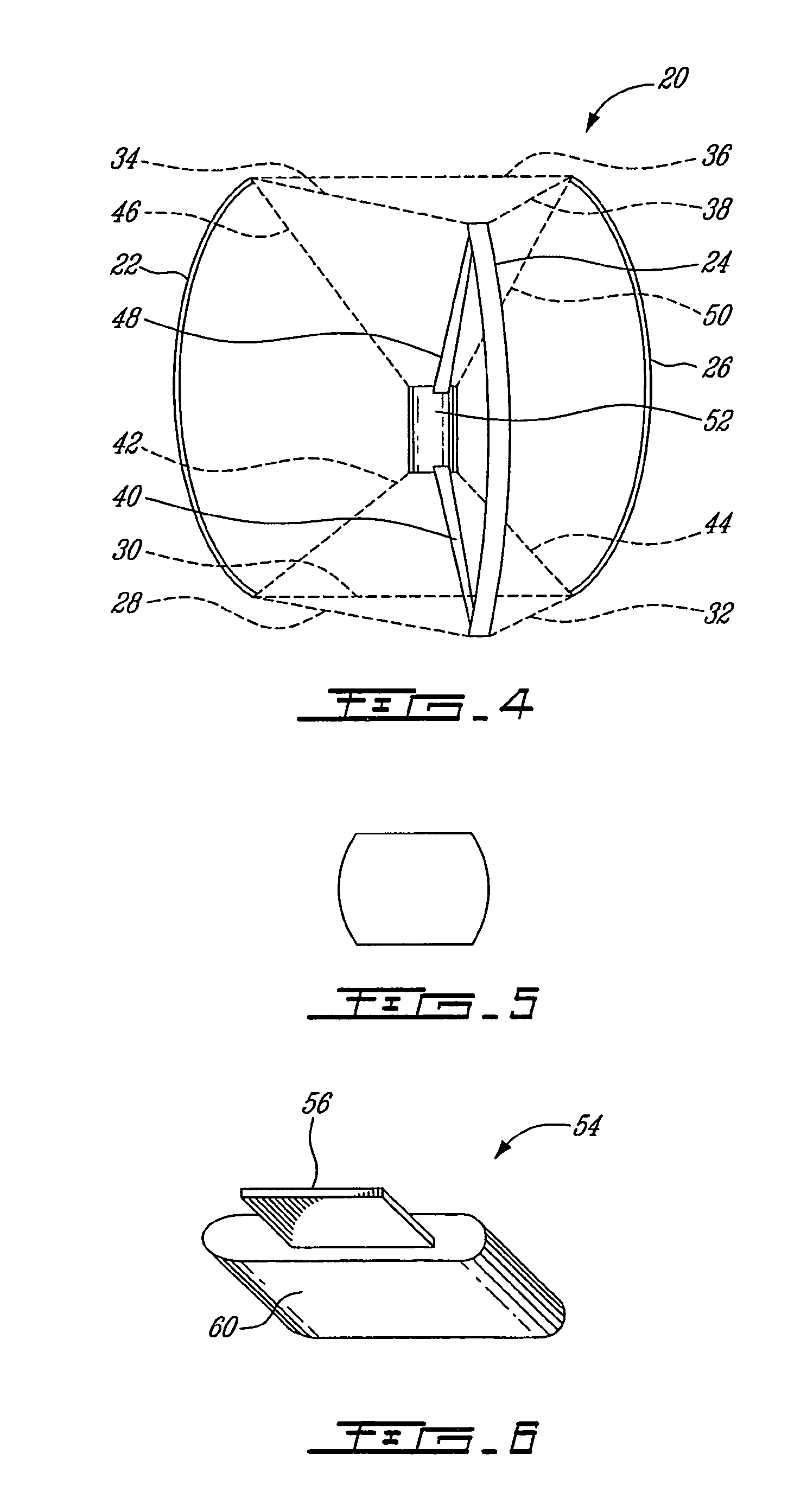
[0045]Referring first to FIGS. 4 and 5 of the appended drawings, a blade attachment structure 20 according to an aspect of the present invention will be described, of the type mentioned hereinabove of a blade connected to a central shaft by means of wing-beams, and based on a fixed geometry enabling an improved wind catching section.

[0046]The blade attachment structure 20 includes three blades 22, 24, 26, two sets of horizontal wing-beams 28, 30, 32 and 34, 3638 under tension and two sets of securing elements 40, 42, 44 and 46, 48, 50.

[0047]The sets of horizontal wing-beams each have a triangular configuration, one set (wing-beams 34, 36, 38) being located on top of the blade attachment...


PUM


Abstract

The present invention provides a structure comprising a blade attachment, a blade structure, an integrated driving shaft/generator for a wind system such as a vertical axis windmill, and a self erecting structure for such a wind system, together with an erecting method thereof.

Description

FIELD OF THE INVENTION[0001]The present invention relates to windmills. More specifically, the present invention is concerned with a vertical axis windmill and to a self-erecting structure therefor.BACKGROUND OF THE INVENTION[0002]Historically, hydro and wind powers were among the first energy sources to be exploited by mankind. After a period of time when other forms of energy sources have cast a shadow on those, there is nowadays a renewed interest in energy conversion systems operable by renewable energy resources such as wind for instance.[0003]Compared to hydropower generation, power generated by means of a windmill generally requires less civil works, depending on the method used to mount and anchor the windmill, and the impact on the environment is minimal.[0004]Generally speaking, wind energy is used through two basic types of windmills. On the one hand, the vertical axis windmills are omni-directional, i.e. they are capable of reacting to the winds from any direction, and t...

Claims


Application Information

Patent Timeline
IPC IPC(8): F03D3/06F03D9/25F03D13/20
CPCF03D3/061E04H12/182F03D3/064F03D3/065F03D11/04F03D3/062F05B2240/212F05B2240/213F05B2240/214F05B2240/9151F05B2260/40311F05B2260/902Y02E10/728Y02E10/74Y10S415/907F03D13/20F03D9/25F03D13/10F03D15/10
Inventor DERY, JACQUELINMONDOU, LAURENT
Owner DERMOND
Why Eureka
Try Eureka