Maritime energy generating device

a technology of energy generation device and maritime island, which is applied in the direction of artificial islands, water acting propulsive elements, propulsive elements, etc., can solve the problems of energy generation device overturning, saving money, and increasing the reliability of operation even further

Inactive Publication Date: 2005-12-27
LAURITSEN PER
View PDF11 Cites 51 Cited by
  • Summary
  • Abstract
  • Description
  • Claims
  • Application Information

AI Technical Summary

Benefits of technology

[0051]It should be mentioned that the weather conditions on the mounting locations will generally vary but not from one second to another and this means that the requirements to the control systems neutralizing the movements before transferring them to the energy generating device will be stable. Also, the change in movements will not be significant for long periods of time and the corresponding control will therefore be equally limited in relation to the degree and swiftness of counter-measures. Generally, the angle of the rotor may be changed very quickly allowing quick responses to changes in e.g. the wind force. The shifting of liquid in the foundation will be advantageous in relation to relatively stable movements of the sea.

Problems solved by technology

Also, it saves money and increases reliability of operation even further since the yaw system presents an inherent risk of mechanical break-down.
Such a break-down may cause the energy generating device to overturn if the break-down means that yawning is impossible while the generating device is fixedly anchored.

Method used


Image

  • Maritime energy generating device
  • Maritime energy generating device
  • Maritime energy generating device

Examples


Embodiment Construction

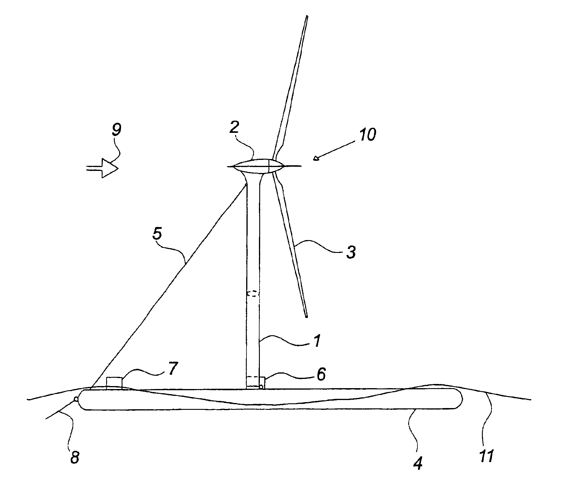
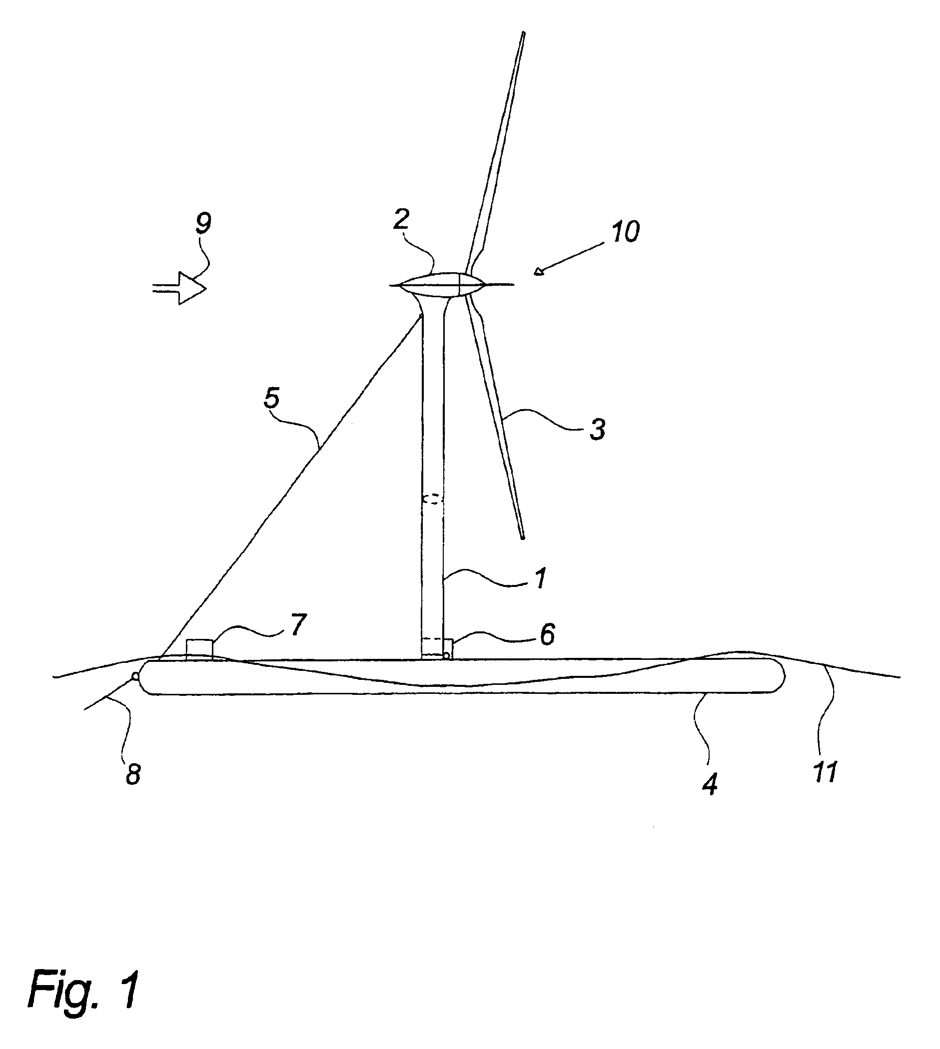
[0061]FIG. 1 shows an example of an embodiment of a maritime energy generating device including a windmill 10 generating electricity which is suitable for mounting at a location at sea, at a lake, an inlet or another water area of a certain depth.

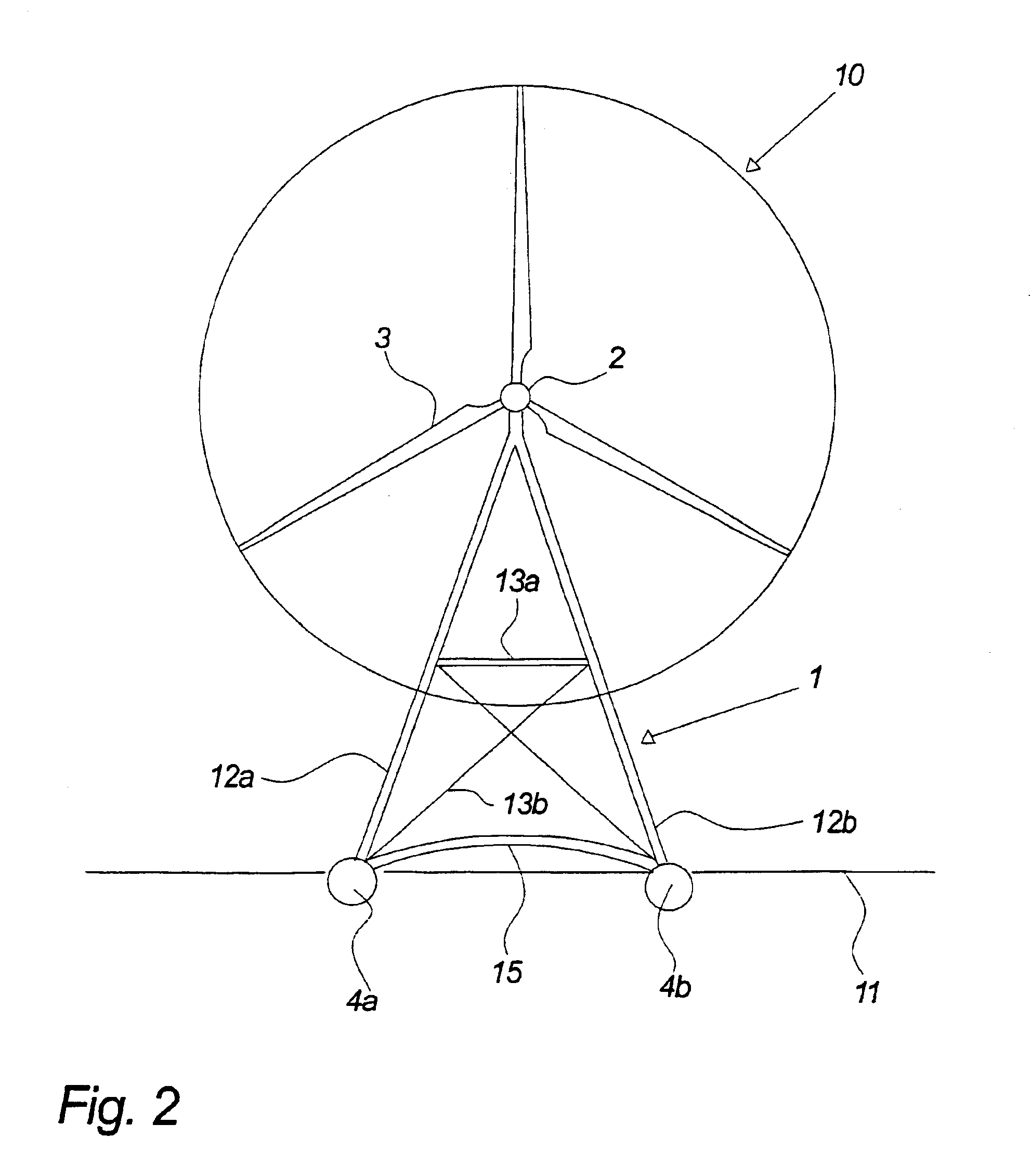
[0062]The foundation 4 of the energy generating device is built as a raft comprising two cylindrical carrying pontoons 4a, 4b which have been mutually connected by a number of crossbars 15. However, it will also be possible to construct the raft in a different way, including the use of several carrying pontoons or alternatively with only one hull, which should naturally be in an essentially even plane below the water surface and have a certain size in order to provide the necessary stability.

[0063]The raft should be designed to lie so deep in the water that large waves can wash over it. In this manner, it is possible to stabilize the windmill at high seas.

[0064]The location of the raft in the water, incl. depth and heeling in the long and t...


PUM


Abstract

A maritime energy generating device including a windmill mounted on a floating foundation, the windmill having a machine compartment mounted at the top of a tower and the foundation being fixed to the bottom of a water body by a connection and including two tanks and a unit for shifting liquid between the tanks and the tanks and the surroundings.

Description

BACKGROUND OF THE INVENTION[0001]The present invention relates to a maritime energy generating device.[0002]So far, windmills for mounting at sea have been developed in accordance with the concept of windmills on land. This means that the windmills generally correspond to the windmills on land with the exception that their foundation is fixedly anchored to the bottom of the sea and of larger dimensions which also makes them more expensive than corresponding foundations on land. The reason for the expensive foundations is that they must raise the windmill to a level corresponding to that of the sea depth and add the risk level at high tide while also being dimensioned for, hummocking, storms, upward pressure etc. Thus, the windmill foundations for windmills at sea are quite expensive.[0003]Another significant added cost associated with windmills at sea stems from the fact that the work with the foundation and the mounting of the windmill must take place at sea and often far away from...

Claims


Application Information

Patent Timeline
Patent Type & Authority Patents(United States)
IPC IPC(8): F03D13/25
CPCF03D11/04E02B2017/0091F05B2240/93F05B2240/95Y02E10/727Y10S415/908B63B2035/446F03D13/25Y02E10/72
Inventor LAURITSEN, PER
Owner LAURITSEN PER
Why Eureka
Try Eureka