
Telescoping guide catheter with peel-away outer sheath

a technology of telescoping guide and outer sheath, which is applied in the field of telescoping guide catheters, can solve the problems of increasing the difficulty of guiding a catheter to its destination, complicated end goal, and often spent by the physician

Inactive Publication Date: 2005-12-27
CARDIAC PACEMAKERS INC
View PDF29 Cites 65 Cited by
  • Summary
  • Abstract
  • Description
  • Claims
  • Application Information

AI Technical Summary

Benefits of technology

[0018]The outer guide is removed by separating the guide handle into at least two sections to split the outer guide along the longitudinal pre-stress line. The outer guide is further split along the longitudinal pre-stress line by retracting the outer guide in a proximal direction relative to the inner guide. The inner guide secures the payload against dislodgment during outer guide retraction.
[0019]Another embodiment of the method involves distally advancing the outer guide over the inner guide to seat the outer guide in the coronary sinus after finding and cannulating the patient's coronary sinus. The inner guide is proximally retracted to remove the inner guide from the outer guide. The payload is then inserted through the proximal end of the outer guide to insert the payload into the patient's coronary sinus. The outer guide is removed by separating the guide handle into at least two sections to split the outer guide along the longitudinal pre-stress line. Then, retracting the outer guide in a proximal direction relative to the payload further splits the outer guide along the longitudinal pre-stress line.

Problems solved by technology

This endeavor, however, is complicated by the fact that the location of the coronary sinus ostium may vary appreciably from one patient to another, especially among patients with diseased hearts.
This further increases the difficulty of guiding a catheter to its destination.
Presently, a considerable amount of time is often spent by the physician when manipulating such catheters within cardiac structures, such as the right atrium, simply trying to locate an anatomical feature of interest, such as the coronary sinus ostium.
However, a stiffer catheter is more prone to accidental dislodgment of payloads, such as pacing leads, when the catheter is retracted.

Method used


Image

  • Telescoping guide catheter with peel-away outer sheath
  • Telescoping guide catheter with peel-away outer sheath
  • Telescoping guide catheter with peel-away outer sheath

Examples


Embodiment Construction

[0034]In the following description of the illustrated embodiments, references are made to the accompanying drawings which form a part hereof, and in which is shown by way of illustration, various embodiments in which the invention may be practiced. It is to be understood that other embodiments may be utilized, and structural and functional changes may be made without departing from the scope of the present invention.

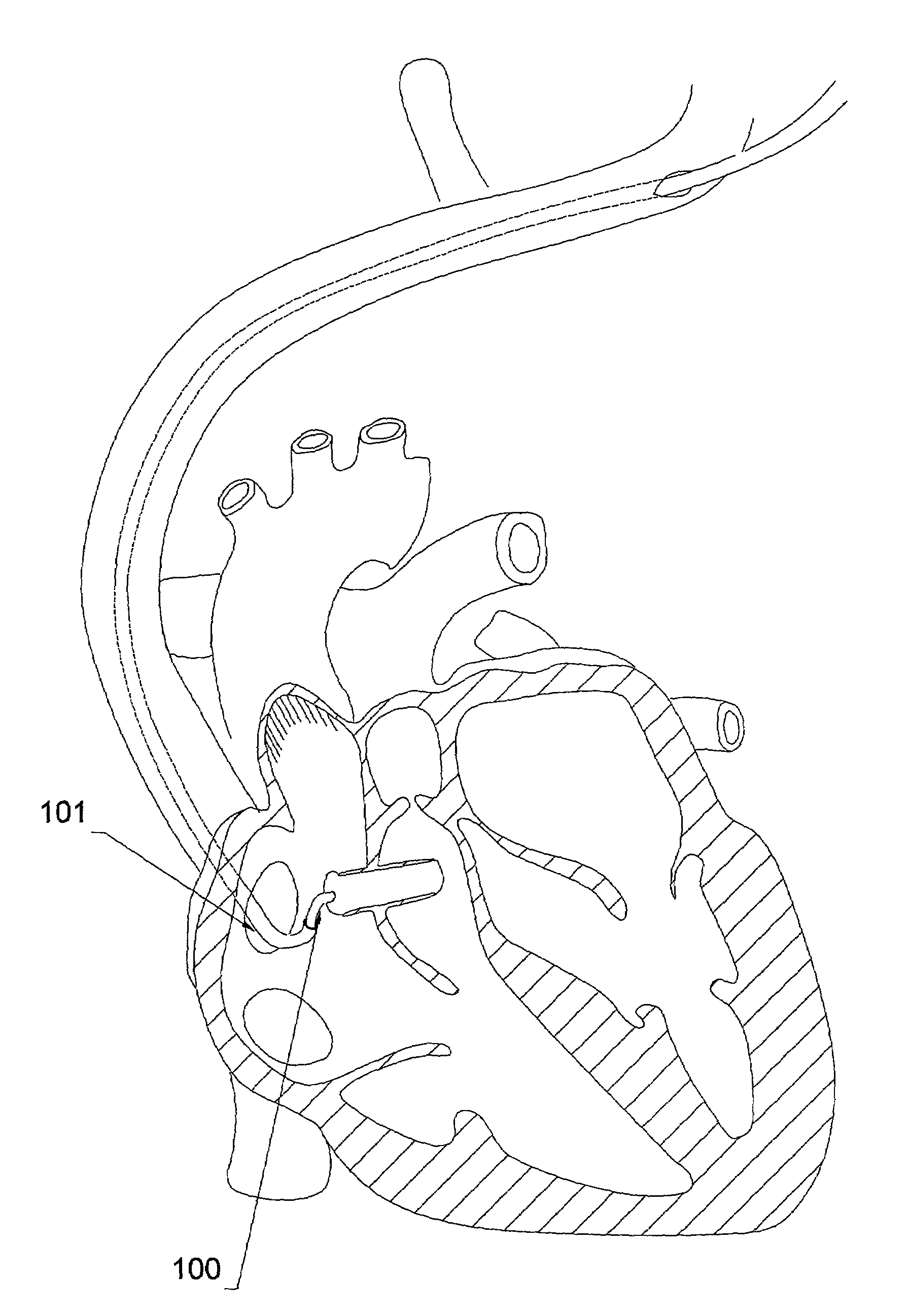
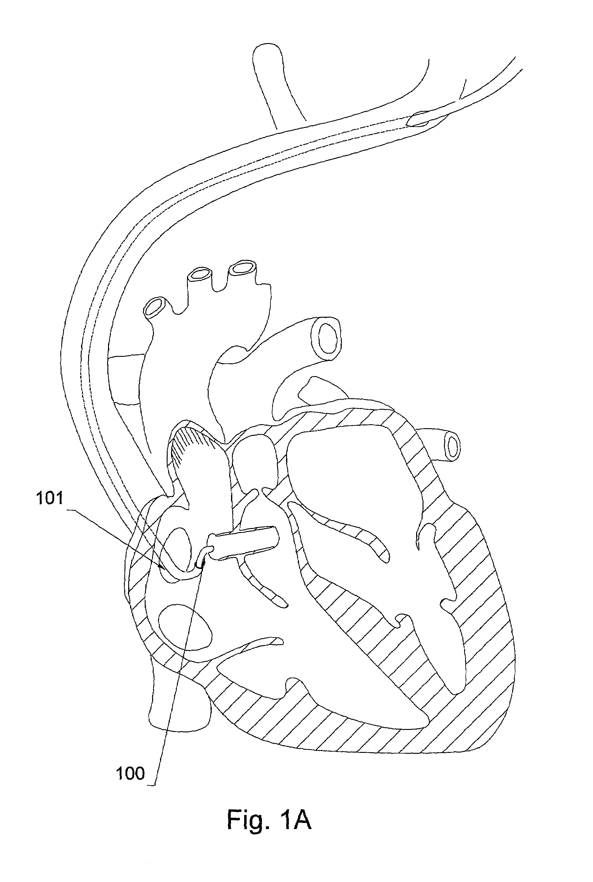
[0035]With reference to FIG. 1A, a distal end of a guide catheter is illustrated in accordance with an embodiment of the present invention. The guide catheter includes an inner guide 100 and an outer guide 101. The guide catheter is shown deployed within a patient's heart, accessing the coronary sinus via the right atrium. A distal end of the inner guide 100 extends from the outer guide 101 as the inner guide 100 is advanced towards the coronary sinus ostium.

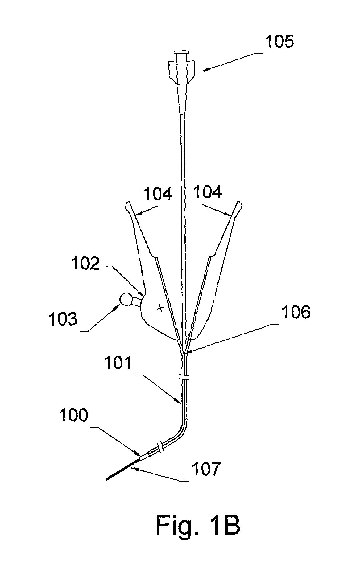
[0036]Turning now to FIG. 1B, a guide catheter is shown embodying features of the present invention. The inner gui...


PUM


Abstract

A guide catheter employs a retractable inner guide movably disposed within an open lumen of a splittable outer guide. The outer guide includes a longitudinal pre-stress line extending from distal to proximal ends. The inner guide includes an open lumen adapted to receive a payload. The inner guide is translatable and rotatable relative to the outer guide. The guide catheter further includes a proximally attached guide handle which is separable into at least two sections. Separation of the guide handle splits the proximal end of the outer guide. Proximal outer guide retraction continues the splitting of the outer guide along the longitudinal pre-stress line.

Description

FIELD OF THE INVENTION[0001]The invention relates generally to guide catheters, and more particularly to dual-sheath, telescoping guide catheters having a peel-away outer sheath used to locate and cannulate the coronary sinus of a patient's heart.BACKGROUND OF THE INVENTION[0002]Guiding catheters are instruments that allow a physician to locate and cannulate vessels in a patient's heart for preforming various medical procedures, including venography and implanting of cardiac pacing devices. Cannulating heart vessels requires navigating a small diameter, flexible guide through the convoluted vasculature into a heart chamber, and then into a destination heart vessel. Once the destination heart vessel is reached, the catheter acts as a conduit for insertion of payloads into the vessel.[0003]A commonly accessed destination vessel for cardiac pacing lead insertion is the coronary sinus. A pre-shaped guiding catheter is typically used to blindly locate the coronary sinus ostium. This ende...

Claims


Application Information

Patent Timeline
Patent Type & Authority Patents(United States)
IPC IPC(8): A61M25/06A61N1/05
CPCA61M25/0668A61N1/056A61M2025/0175A61N2001/0578
Inventor MANNING, FRANK E.PETERSON, CHARLES R.GRAHAM, HOWARD P.
Owner CARDIAC PACEMAKERS INC
Learn More