Keystroke structure (1)

a keystroke and structure technology, applied in the field of keystroke structure, can solve the problems of troublesome and complex assembly, high manufacturing cost, complex components, etc., and achieve the effect of saving manufacturing cost, simple structure and easy and fast assembly

Inactive Publication Date: 2005-12-27
TSAI LAI CHENG
View PDF7 Cites 50 Cited by
  • Summary
  • Abstract
  • Description
  • Claims
  • Application Information

AI Technical Summary

Benefits of technology

[0016]It is therefore a primary object of the invention to provide a keystroke structure (1) comprises a baseplate with insert holes are considerably spaced; the baseplate further comprises a membrane circuit board; an electrically conductive and round in shape resilient body is on the circuit board, a first key frame and a second key frame are on the rim of the resilient body; the first key frame and the second key frame comprise two protruding hinged arms at one end and two extending posts at the other end; the posts comprise a shaft lever respectively; the shaft levers can thread insert the holes on the hood frame; furthermore, the posts comprise a protruding tubes each where they are connected with the first key frame and the second key frame; the tubes comprise a through holes each which the hinged arms thread such that the first key frame and the second key frame can be connected in “Y” shape. A key cap is inserte

Problems solved by technology

Conventional structure has the following disadvantages:1. Complex components and high manufacturing cost.2. In installation, the post frames of the bridgeboard and the shaft levers on both ends of tenon frame are required to sleeve on the bridgeboard, which makes assembling a troublesome and complex job.3. Board grooves ar

Method used


Image

  • Keystroke structure (1)
  • Keystroke structure (1)
  • Keystroke structure (1)

Examples


Embodiment Construction

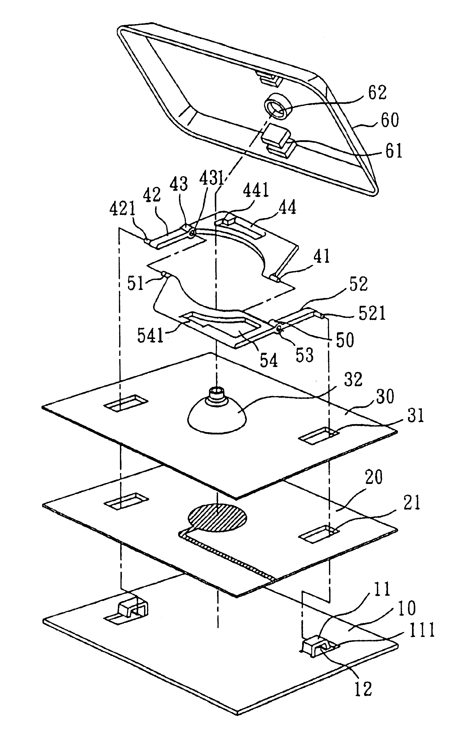
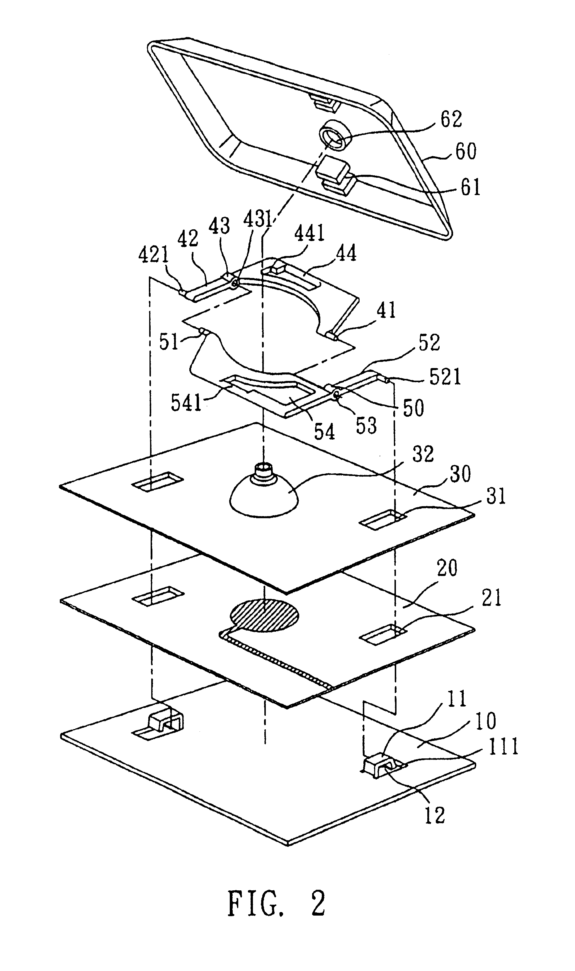
[0027]As shown in FIG. 2, the structure in the present invention comprises a baseplate 10; the baseplate 10 comprises an inverse “U” shape hood frame 11; the hood frame 11 comprises a gap 111 at one end and an insert hole 12 in the middle; these insert holes 12 are considerably spaced; the baseplate 10 further comprises a membrane circuit board 20; the membrane circuit board 20 is connected with outside via a circuit; a through hole 21 is provided on the membrane circuit board 20 at a location corresponding to the insert hole 12; a pad 30 is stacked over the membrane circuit board 20; an open hole 31 is provided on the pad 30 at a location corresponding to the through hole 21; a resilient body 32 is provided on the pad 30; the resilient body 32 is electrically conductive and round in shape.

[0028]Furthermore, a first key frame 40 and a second key frame 50 are on the pad 30; wherein the first key frame 40 and the second key frame 50 comprise two protruding hinged arms 41 and 51 at one...


PUM


Abstract

A keystroke structure (1) comprising a baseplate with insert holes are considerably spaced; the baseplate further comprises a membrane circuit board; an electrically conductive and round in shape resilient body is on the circuit board, a first key frame and a second key frame are on the rim of the resilient body; the first key frame and the second key frame comprise two protruding hinged arms at one end and two extending posts at the other end; the posts comprise a shaft lever respectively; the shaft levers can thread insert the holes on the hood frame; furthermore, the posts comprise a protruding tubes each where they are connected with the first key frame and the second key frame; the tubes comprise a through holes each which the hinged arms thread such that the first key frame and the second key frame can be connected in “Y” shape. A key cap is inserted on the first and the second key frame, while assembly, since the posts have only one end stretch out to the baseplate, the assembly is easier and faster, the structure is simpler to save manufacturing cost. The first and the second key frames are connected together to support each other, the supporting strength is stronger, the slide is smoother.

Description

BACKGROUND OF THE INVENTION[0001]I. Field of the Invention[0002]The present invention relates to a keystroke structure (1) and particularly, to a keystroke structure that can reduce assembling steps and be slidden smoothly.[0003]II. Description of the Prior Art[0004]Heretofore, it is known that notebook computers are much favored and extensively used because they are portable and highly functional in document and data processing. To improve portability, reduce size, thickness and weight for notebook computers, manufacturers are engaged in constant research and development. The thin-type keystroke structure currently used by notebook computer keypads, as shown in FIG. 1, is mostly a scissor-type (or bridging type) supporting structure between key cap and baseplate, which comprises:[0005]a key cap wherein a cap post extends downward in the center of the downward extending cap cover; two horizontal cap sheets that extend down the inner wall on the same side and the two cap hooks that e...

Claims


Application Information

Patent Timeline
IPC IPC(8): H01H3/12H01H13/70
CPCH01H3/125
Inventor TSAI, LAI CHENG
Owner TSAI LAI CHENG
Why Eureka
Try Eureka