Cable tester with insertion loss and return loss estimators

Inactive Publication Date: 2005-12-27
MARVELL ASIA PTE LTD
View PDF11 Cites 99 Cited by
  • Summary
  • Abstract
  • Description
  • Claims
  • Application Information

AI Technical Summary

Benefits of technology

[0011]A physical layer device according to the present invention communicates over a cable. The physical layer device includes a cable tester that determines a cable status, which includes an open status, a short status, and a normal status. The cable tester includes a pretest module that senses activity on the cable and selectively enables testing based on the

Problems solved by technology

Cabling problems can cause a significant amount of network downtime and can require troubleshooting resources, which increase the total cost of ownership.
Conventional cable tests may generate inaccurate results when the cable is terminated by an active link partner that is generating link pulses during a test.
When connecting these network devices to cable, the same types of cabling problems

Method used


Image

  • Cable tester with insertion loss and return loss estimators
  • Cable tester with insertion loss and return loss estimators
  • Cable tester with insertion loss and return loss estimators

Examples


Embodiment Construction

[0065]The following description of the preferred embodiment(s) is merely exemplary in nature and is in no way intended to limit the invention, its application, or uses. For purposes of clarity, the same reference numbers will be used in the drawings to identify the same elements.

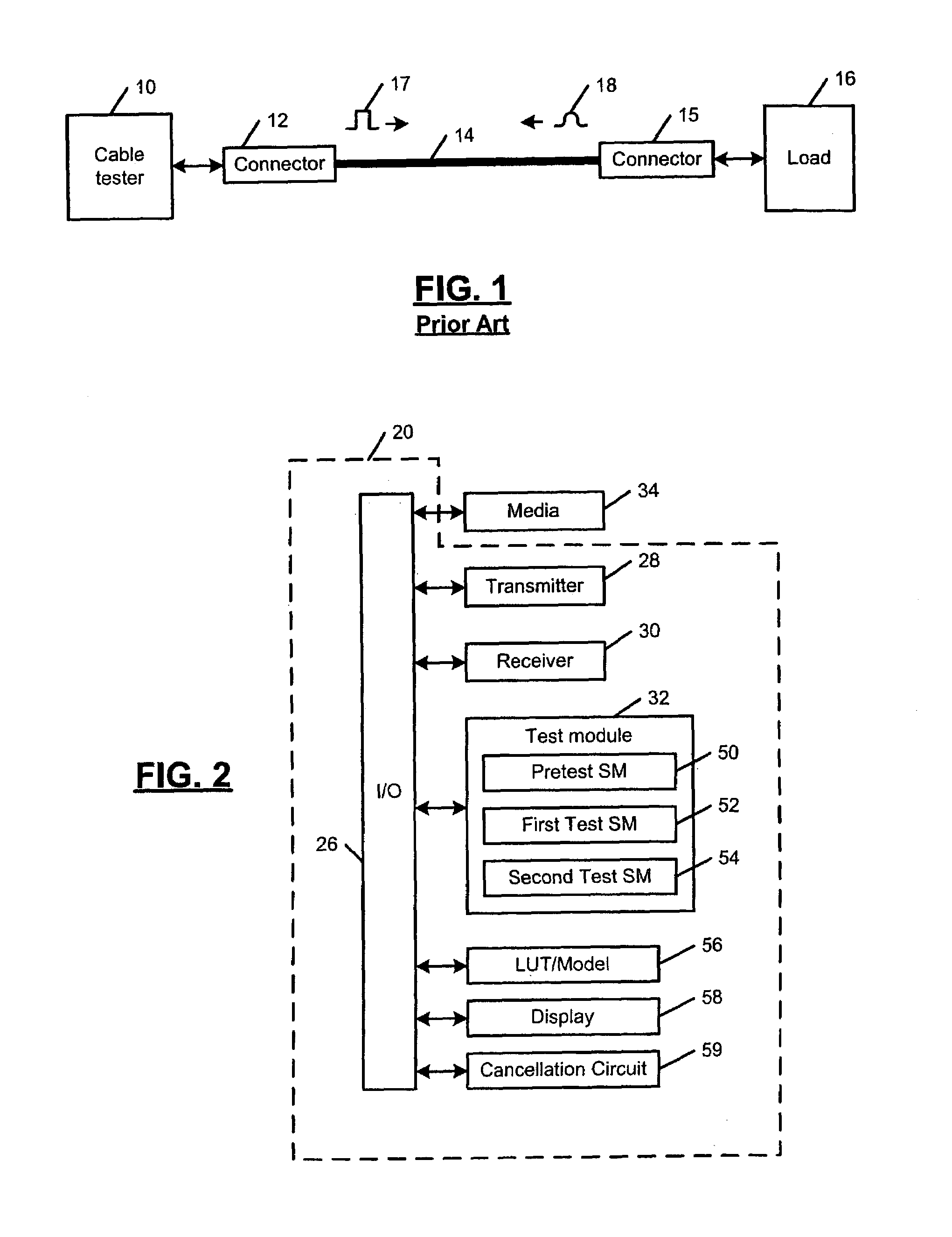
[0066]Referring now to FIG. 2, a cable tester 20 according to the present invention is shown. The cable tester 20 is capable of testing 10 / 100BaseT cable, 1000BaseT cable, and / or other cable media. For example, 10 / 100BaseT includes two pairs of twisted pair wires and 1000BaseT cable includes four pairs of twisted pair wires. A transmitter 28 and a receiver 30 are coupled to the I / O interface 26. A test module 32 includes state machines for testing a media 34 such as cable. The test module 32 can be implemented in combinatorial logic, using discrete circuits, and / or using a processor and memory that executes testing software.

[0067]The test module 32 includes a pretest state machine or module 50. The test modu...


PUM


Abstract

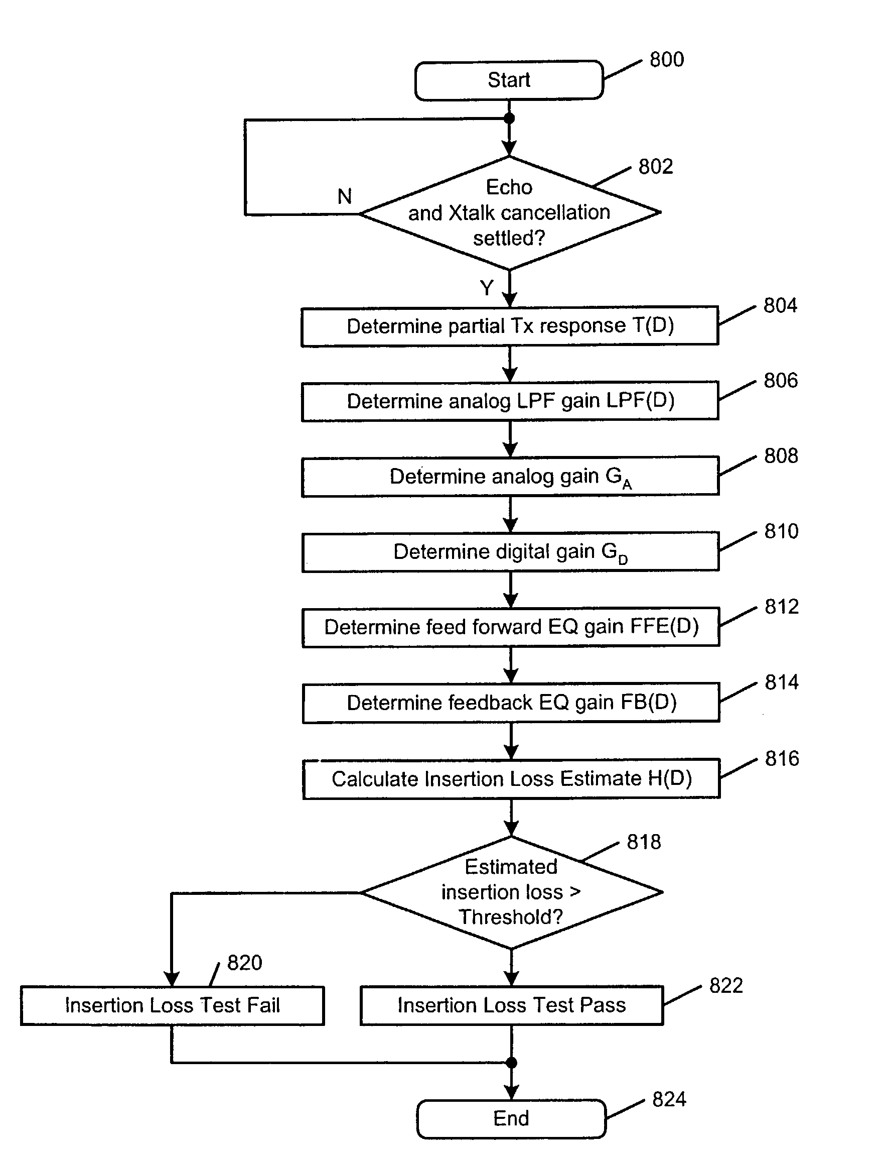
A physical layer device that communicates over a cable comprises a cable tester that determines a cable status, which includes an open status, a short status, and a normal status. The cable tester includes a pretest module that senses activity on the cable and selectively enables testing based on the sensed activity. A test module is enabled by the pretest module, transmits a test pulse on the cable, measures a reflection amplitude, calculates a cable length, and determines the cable status based on the measured amplitude and the calculated cable length. An insertion loss estimator communicates with the cable tester and estimates insertion loss of the cable. A return loss estimator communicates with the cable tester and estimates return loss of the cable based on gain parameters of the physical layer device.

Description

CROSS-REFERENCE TO RELATED APPLICATIONS[0001]This application is a continuation-in-part of U.S. patent application Ser. No. 10 / 331,221, filed Dec. 30, 2002, which is a continuation-in-part of U.S. patent application Ser. No. 10 / 165,467, filed Jun. 7, 2002 now U.S. Pat. No. 6,825,672. The disclosures of the above applications are incorporated herein by reference in their entirety.FIELD OF THE INVENTION[0002]The present invention relates to electronic diagnostic systems, and more particularly to testing equipment for cable used in a network.BACKGROUND OF THE INVENTION[0003]One goal of a network manager is to control total cost of ownership of the network. Cabling problems can cause a significant amount of network downtime and can require troubleshooting resources, which increase the total cost of ownership. Providing tools that help solve cabling problems more quickly will increase network uptime and reduce the total cost ownership.[0004]Referring now to FIG. 1, conventional cable tes...

Claims


Application Information

Patent Timeline
IPC IPC(8): G01R31/08G01R31/11
CPCG01R31/083G01R31/088G01R31/11
Inventor LO, WILLIAMGUO, YIQINGTSUI, TAKLEUNG, TSIN-HOHE, RUNSHENGJANOFSKY, ERIC
Owner MARVELL ASIA PTE LTD
Why Eureka
Try Eureka